

Part of the Yanmar Repair Manuals.
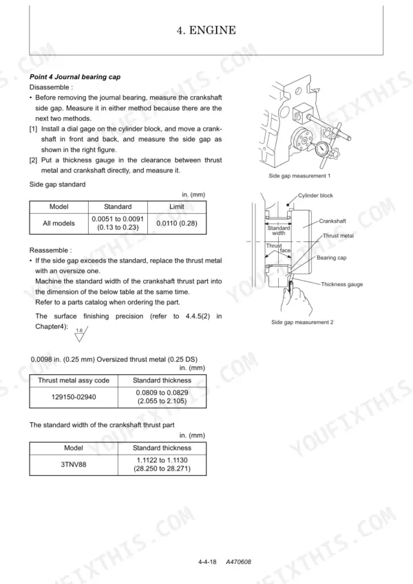
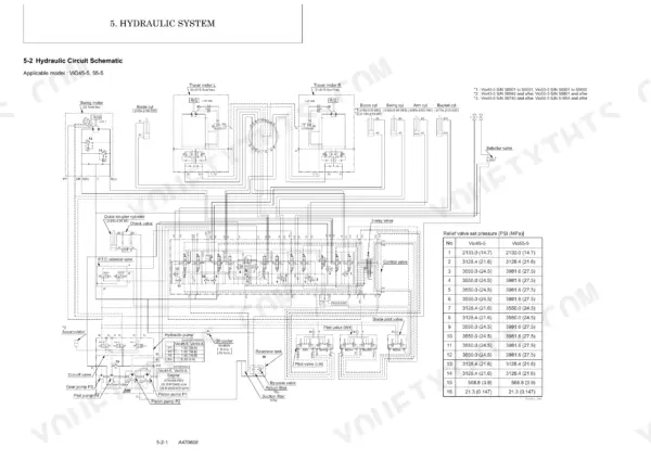
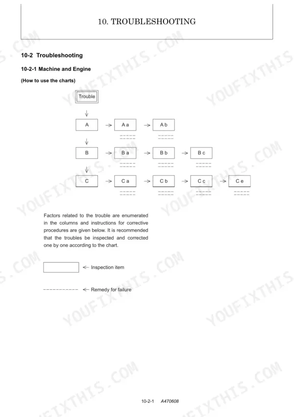
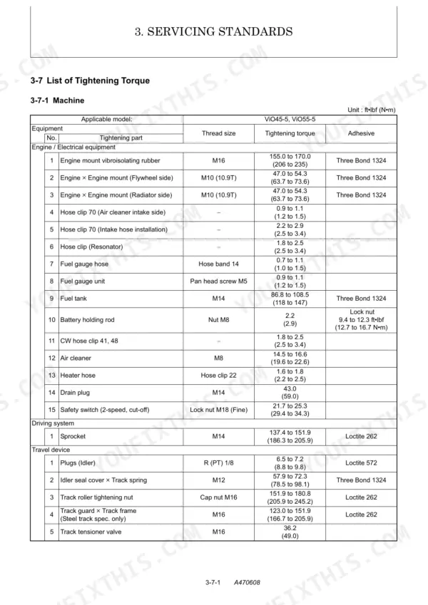
All 568 pages of this Yanmar ViO45-5, ViO55-5 Service Manual PDF are built around one job: returning your compact excavators to factory spec. Inside you get full hydraulic circuit schematics covering boom, arm, bucket, swing, and travel operation, plus wiring diagrams for every electrical circuit on the machine. A complete troubleshooting section, page after page of tightening torque tables, and step-by-step rebuild procedures for the hydraulic pump, control valve, swing motor, and travel motor fill out the remaining pages. Torque the M16 engine mount rubber to 206-235 N·m; set the swivel joint-to-track frame M10 fasteners to 44.1-58.8 N·m with Loctite 262. No more chasing faults blind. Bookmarked and keyword-searchable, this PDF opens on any device and puts the right number in front of you in seconds.
Complete the set for your ViO45-5, ViO55-5
- Parts Catalog: Yanmar ViO55-5 Parts Catalog (Excavator)
What's Inside This Manual
| System | Pages | Key Topics |
|---|---|---|
| Spine Title | 2 | |
| General Cautions for Maintenance Work | 13-26 | 1-1 Correct Work, 1-2 Safety Precautions, 1-3 Preparations, 1-4 Cautions for Disassembly and Reassembly, 1-5 Cautions for Removal and Installation of Hydraulic Equipment |
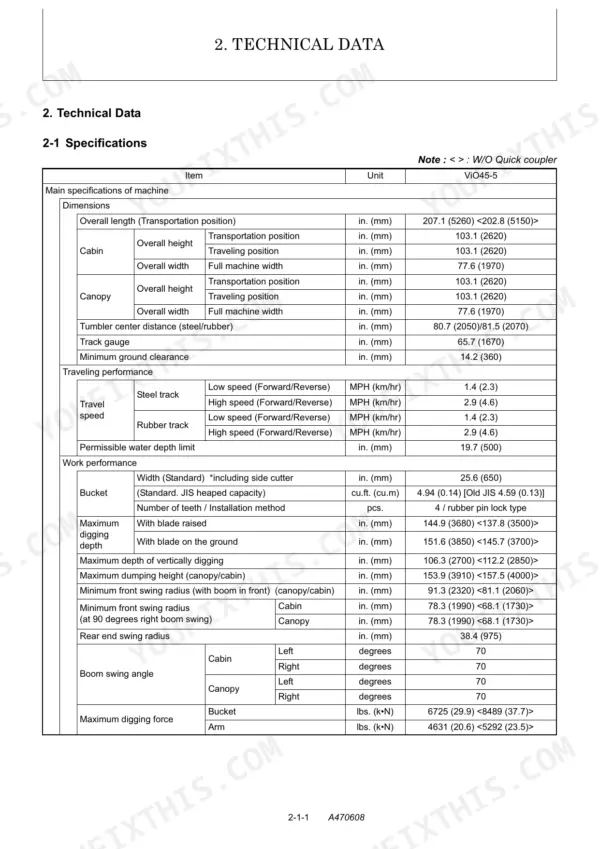
| Technical Data | 27-50 | 2-1 Specifications, 2-2 Outline Drawing and Working Area, 2-3 Weight List of Main Parts, 2-4 Lifting Capacity List |
| Service Standards | 51-72 | 3-1 Machine Performance, 3-2 Engine, 3-3 Undercarriage, 3-4 Controls, 3-5 Hydraulic Equipment, 3-6 Implement, 3-7 List of Tightening Torque |
| Engine | 73-148 | 4-1 General, 4-3 Inspection and Adjustment, 4-4 Engine Body, 4-5 Lubrication System, 4-6 Cooling System, 4-7 Fuel Injection Pump / Governor, 4-8 Electrical Equipment |
| Hydraulic System | 149-192 | Outline (Control Valve Operation, Additional Operation of Control Valve), Hydraulic Circuit Schematic |
| Hydraulic Equipment | 193-398 | 6-1 Hydraulic Pump, 6-2 Control Valve, 6-3 Pilot Valve, 6-4 Swing Motor, 6-5 Travel Motor, 6-6 Blade Control Pilot Valve, 6-7 Solenoid Valve for P.T.O. Operation |
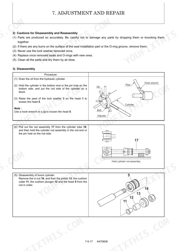
| Adjustment and Repair | 399-512 | 7-1 Electric Equipment of Machine, 7-2 Undercarriage, 7-3 Controls, 7-4 Swing Bearing, 7-5 Hydraulic Equipment, 7-6 Work Implements, 7-7 Cabin |
| Periodic Inspection and Servicing | 513-516 | 8-1 List of Periodic Inspection and Servicing |
| Fuel, Lube Oil and Grease Recommended | 517-520 | Fuel, Engine Oil, Hydraulic Oil, Travel Reduction Gear Oil, Grease, Antifreeze |
| Troubleshooting | 521-562 | 10-1 Non-Breakdowns, 10-2 Troubleshooting |
| Reference Data | 563-568 | 11-1 Dimensions and Specifications for Attachment |
Quick Reference Specifications
| Specification | Value | Page |
|---|---|---|
| Engine mount vibroisolating rubber (M16) tightening torque | 155.0 to 170.0 ft·lbf (206 to 235 N·m) | p. 66 |
| Swivel joint × Track frame (M10) tightening torque | 32.6 to 43.4 ft·lbf (44.1 to 58.8 N·m) | p. 67 |
| Solenoid valve spool clearance | 0.03 mm or less | p. 387 |
| Return filter bypass valve opening pressure | 21.3 PSI (0.147 MPa) | p. 150 |
| Fan belt tension (deflection) | 0.39 to 0.59 in. (10 to 15 mm) / 72.3 lbf. (98 N) | p. 88 |
| Heater hose clip (Hose clip 22) tightening torque | 1.6 to 1.8 ft·lbf (2.16 to 2.45 N·m) | p. 417 |
| Travel alarm switch clearance | 0.02 in. (0.5 mm) or less | p. 442 |
| Hydraulic cylinder extension and retraction stroke for air release | 1.97 to 3.9 in. (50 to 100 mm) from each stroke end | p. 23 |
| Engine Oil Capacity (Total) | 9.4 Qts (8.9 L) | p. 87 |
| Hydraulic Oil Tank Capacity (Total) | 16.9 Gals (64 L) | p. 30 |
| Cooling Water Capacity (Total) | 7.1 Qts (6.7 L) | p. 517 |
| Intake Valve Clearance (Cold Engine) | 0.0059 to 0.0098 in (0.15 to 0.25 mm) | p. 37 |