

Part of the Yanmar Repair Manuals.
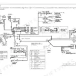
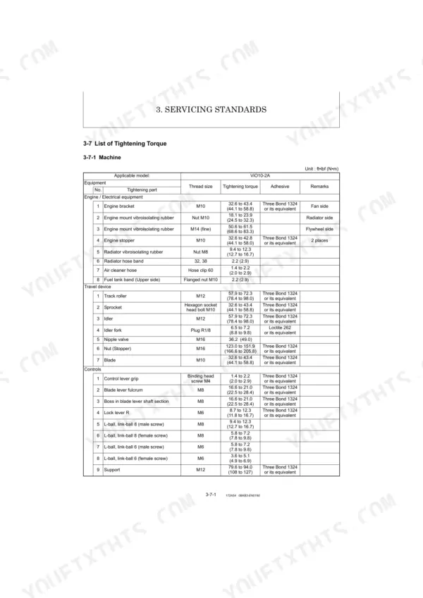
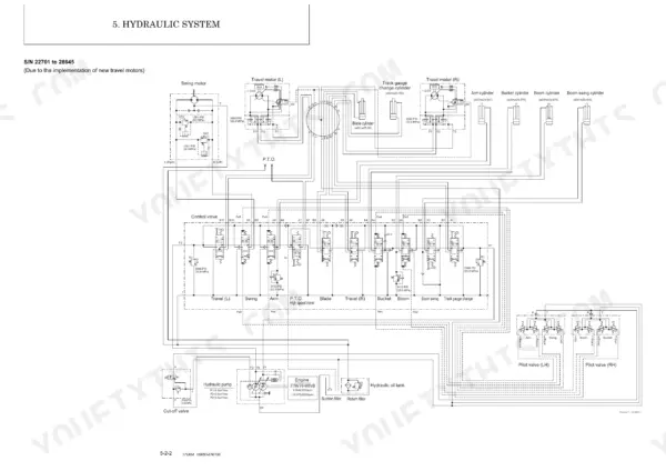
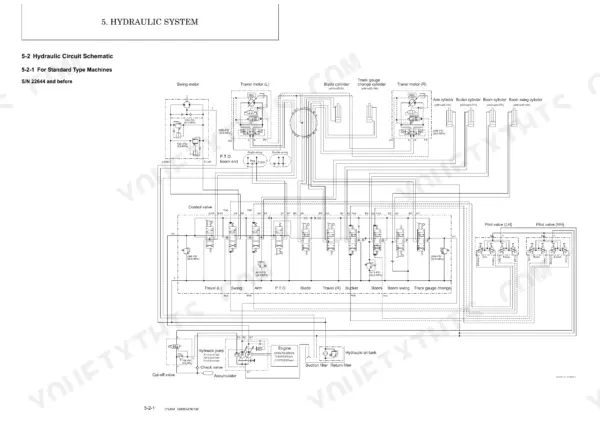
Need the factory specs for your Yanmar ViO10-2A? This 450-page service manual PDF covers the compact excavator from hydraulic pump rebuild to engine disassembly, straight from Yanmar factory data. Inside: a full hydraulic circuit schematic tracing fluid routing through every function, boom swing, blade, track gauge change, and PTO. You also get the complete wiring diagram with monitor and alarm system coverage, a torque table running from machine fasteners through engine hardware, and a troubleshooting section that walks fault isolation step by step. Set your M20 boom cylinder U-nut to 294.3-343.0 N-m; the M10 engine bracket bolts torque to 44.1-58.8 N-m. Your machine is down. Bookmarked by section and keyword-searchable: grab your tablet, walk to the machine, and start wrenching.
What's Inside This Manual
| System | Pages | Key Topics |
|---|---|---|
| Spine Title | 2 | |
| General Cautions for Maintenance Work | 11-24 | Correct Work, Safety Precautions, Preparations, Cautions for Disassembly and Reassembly, Cautions for Removal and Installation of Hydraulic Equipment |
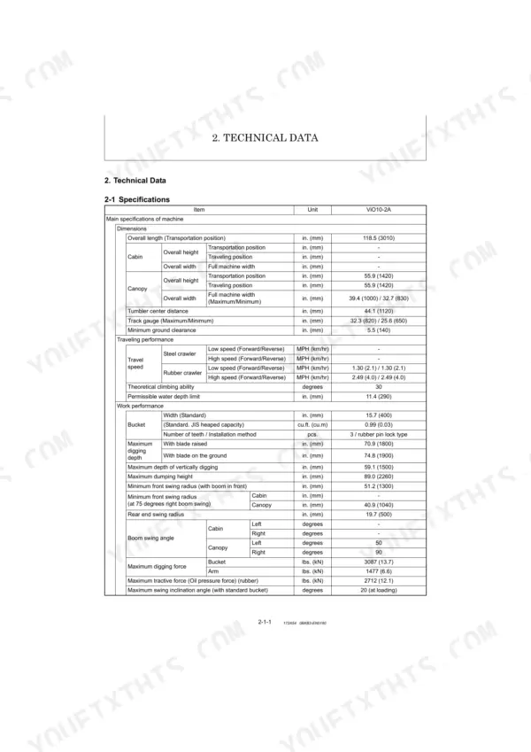
| Technical Data | 25-38 | 2-1 Specifications, 2-2 Outline Drawing and Working Area, 2-3 Weight List of Main Parts, 2-4 Lifting Capacity List |
| Service Standards | 39-58 | Machine Performance, Engine, Undercarriage (Rubber Crawler Specifications), Controls, Hydraulic Equipment (Hydraulic Cylinders) |
| Engine | 59-100 | Measurement |
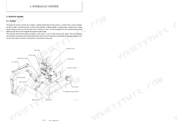
| Hydraulic System | 101-136 | Outline (Control Valve Operation), Hydraulic Circuit Schematic (for Standard Type Machines) |
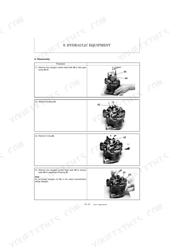
| Hydraulic Equipment | 137-308 | Hydraulic Pump (S/N: 28645 and Before, 28646 and Above), Control Valve, Pilot Valve, Cut-Off Valve, Swing Motor, Travel Motor (S/N: 22644 and Before, 22701 and Above) |
| Adjustment and Repair | 309-400 | Electrical Equipment and Engine of Machine (Parts Layout of Electrical Equipment, Monitor and Alarm Systems, Wiring Diagram, Circuit Description of Engine Start and Stop, Removal and Reinstallation of Engine, Removal and Reinstallation of Starter Motor, Removal and Reinstallation of Fuel Injection Pump, Removal and Reinstallation of Fuel Tank, Removal and Reinstallation of Radiator) |
| Periodic Inspection and Servicing | 401-404 | 8-1 List of Periodic Inspection and Servicing |
| Fuel, Lube Oil and Grease Recommended | 405-408 | Engine Oil, Travel Reduction Gear Oil, Hydraulic Oil, Fuel, Engine Cooling Water, Fuel Tank |
| Troubleshooting | 409-446 | 10-1 Non-Breakdowns, 10-2 Troubleshooting |
| Reference Data | 447-450 | 11-1 Specifications for Attachment |
Quick Reference Specifications
| Specification | Value | Page |
|---|---|---|
| Engine bracket (M10) tightening torque | 32.6 to 43.4 ft•lbf (44.1 to 58.8 N•m) | p. 53 |
| Track roller (M12) tightening torque | 57.9 to 72.3 ft•lbf (78.4 to 98.0 N•m) | p. 53 |
| Hydraulic hose SAE J517,100R1 (02) Inner dia. | 0.25 in. (6.3 mm) | p. 17 |
| Hydraulic hose SAE J517,100R1 (02) Working pressure | 2489 PSI (17.2 MPa) | p. 17 |
| Oil/water separator type | Mesh filter screen | p. 30 |
| LO filter type | Full flow filter | p. 30 |
| LO filter filtration area | 124.1 sq.in. (800 sq.cm) | p. 30 |
| Air cleaner type | Cyclone type | p. 31 |
| Air cleaner filtration area | 9.7 sq.ft. (0.9 m2) | p. 31 |
| Radiator hose band tightening torque | 2.2 ft•lbf (2.9 N•m) | p. 53 |
| Rubber crawler (A) wear limit | 0.31 in. (8 mm) | p. 47 |
| Idler & shaft (B) wear limit | 1.02 in. (26 mm) | p. 47 |