
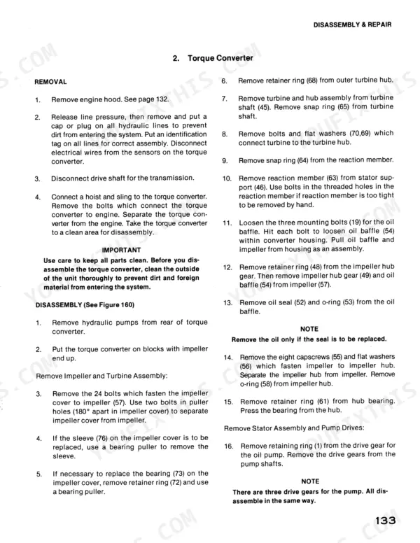
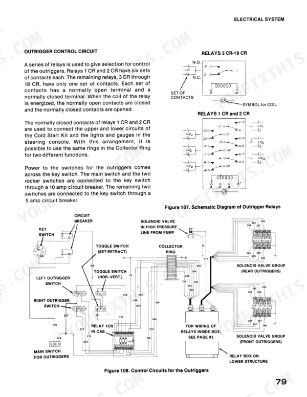
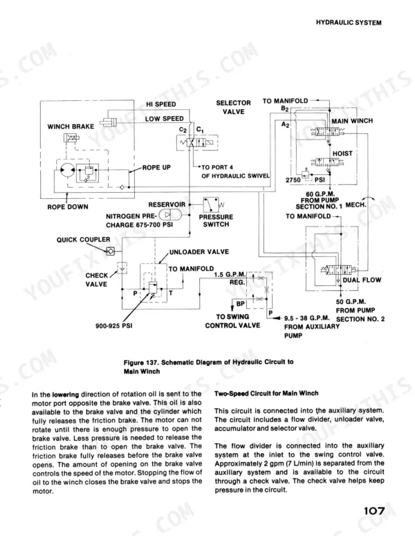
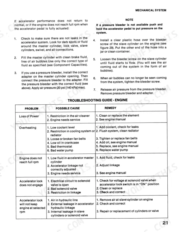
Part of the Case Repair Manuals.
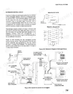
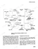
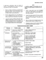
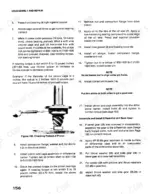
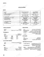
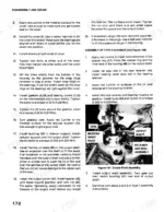
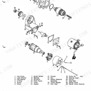
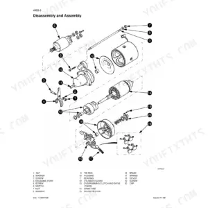
All 276 pages of this Case 5550 service manual PDF (OEM #S406249) point at one machine: the 5550 Cruz-Crane, from turntable bearing to steering orbitrol. You get factory wiring diagrams for the collector ring and outrigger relays, hydraulic schematics tracing every circuit from the main pump through the swing motor, and troubleshooting charts for the air system, transmission, winches, and electrical faults. Exploded views back up a full section of step-by-step procedures on your Braden and Gearmatic winches, torque converter, and hoist cylinders. Both main relief valves are set at 2750 psi (18 960 kPa), and pump section 1 feeds the main winch at 60 gpm (227 L/min). A crane that won't swing is just scrap iron in the way. This bookmarked PDF opens on any laptop, tablet, or phone; carry it out to the machine and get wrenching.
What's Inside This Case 5550 Cruz - Crane Manual
| System | Pages | Key Topics |
|---|---|---|
| General | 5-11 | Machine Identification, Engine Identification, Direction References, Boom, Hoist Cylinders, Main Winch |
| Preventive Maintenance | 12-17 | Sound Reduction Insulation, Spark Arresting Mufflers, Hydraulic Oil Recommendations, Maintenance Chart, Grease Fittings |
| Mechanical System | 18-61 | Engine, Accelerator, Torque Converter, Transmission, Turntable Swing, Winches |
| Air System | 62-71 | Air Compressor, Air Reservoir, Brake Valve, Air Swivel, Relay Valve, Double Check Valve |
| Electrical System | 72-87 | Alternator, Voltage Regulator, Battery, Collector Ring, Circuit Breakers, Outrigger Relays |
| Hydraulic System | 88-132 | Main Hydraulic Pump, Auxiliary Hydraulic Pump, Hydraulic Swivel, Main Control Valves, Steering Orbitrol, Swing Motor |
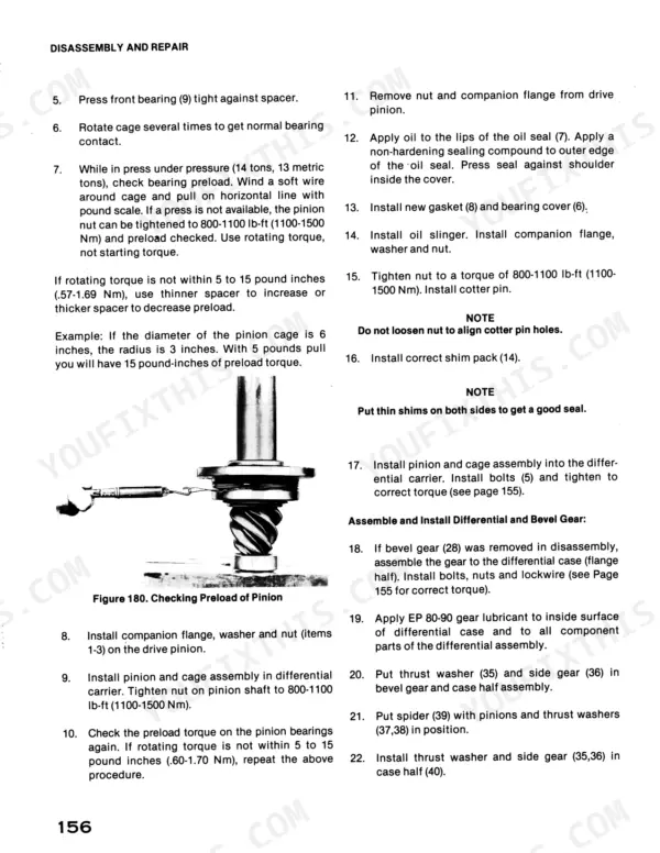
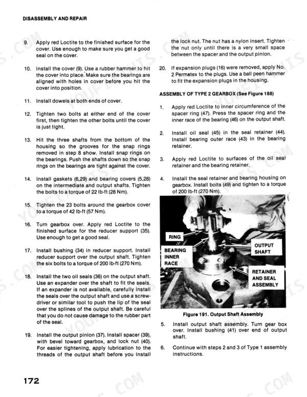
| Disassembly and Repair | 133-210 | Torque Converter, Transmission, Swing Gearbox, Turntable Bearing, Braden C2H16 Winch, Braden PD10-D Winch, Gearmatic Gh-85 Winch |
| Governor | 211-249 | Drain, Automatic |
| Hoist | 250-254 | Hoist Cylinders, Counterbalance Valves, Main Winch, Brake Valve, Winch Motor |
| Oscillation, Axle Lockout | 255 | Oscillation Lockouts, Hydraulic Cylinders, Solenoid Valves, Axle Lockout Circuit |
| Steering | 255-273 | Steering Circuit, Steering Orbitrol, Flow Divider, Steering Selector Valve, Steering Lock Valve |
| Torque Charts | 274-276 | Jic Swivel Nuts, Grade 5 Capscrews, Grade 8 Capscrews, Axle Torque Specifications, Transmission Torque Specifications |
Quick Reference Specifications
| Specification | Value | Page |
|---|---|---|
| Main Pump Section 1 Rated Output | 60 gpm (227 L/min) | p. 13 |
| Main Pump Section 2 Rated Output | 50 gpm (189 L/min) | p. 13 |
| Circuit breaker rating | 10 AMP | p. 71 |
| Circuit breaker | 10 amp | p. 84 |
| Main relief valve pressure setting | 2750 psi (18 960 kPa) | p. 94 |
| Adjustment per quarter turn of adjusting screw | 200 psi (1 380 kPa) | p. 95 |
| Auxiliary pump output | 34 gpm (128 L/min) | p. 119 |
| Torque for 3/8 Grade 5 Fine Threads | 26-29 LB-FT | p. 145 |
| Torque for 3/8 Grade 5 Coarse Threads | 23-25 LB-FT | p. 145 |
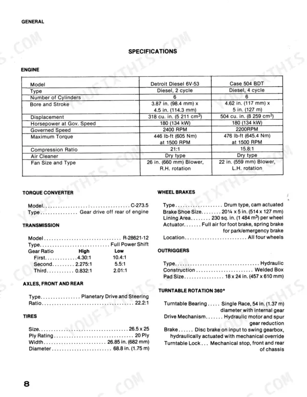
| Detroit Diesel 6V-53 Governed Speed | 2400 RPM | p. 10 |
| Tire Pressure | 65 psi | p. 13 |
| Fuel Tank Capacity | 105 gal | p. 13 |
Case 5550 Cruz - Crane Common Problems This Manual Covers
Case 5550 Cruz-Crane hydraulic pump noisy under load, boom and winch functions slow
Check the hydraulic oil level and look for foam in the tank; foam means air is entering the suction side. Tighten suction fittings and replace cracked hoses. Test main pump section 1 output at full throttle; output well below 60 gpm (227 L/min) points to internal wear. Work the noise chart in the Hydraulic System section starting on page 88.
Manual Section: Hydraulic System Troubleshooting p. 88Outriggers extend slowly, or one horizontal or vertical cylinder will not move at all
Verify power reaches the outrigger switch through the 10 amp circuit breaker described on page 84; a tripped breaker kills the whole circuit even when hydraulics are healthy. If power checks good, gauge the system: both main relief valves are set at 2750 psi (18 960 kPa), covered on page 94. Low pressure or a leaking valve spool slows every cylinder.
Manual Section: Electrical Troubleshooting p. 84Work lights and gauge indicators dead while engine and hydraulics operate normally
Check bulbs first, then the circuit breakers; the 10 AMP breaker on page 71 protects the brake lights and low air pressure indicators. Trace broken leads with the wiring diagram on page 81 before condemning components. Inspect the collector ring under the turntable; worn or dirty brushes cut power to everything above the swing bearing.
Manual Section: Electrical Troubleshooting p. 84Turntable swings slowly or keeps rotating after the control lever is released
Test the crossover relief cartridges at the swing motor; they must hold 1900 ± 50 psi (13 100 ± 340 kPa), covered on page 122. A weak cartridge lets oil bypass the motor and the turntable drifts. Verify the auxiliary pump delivers about 34 gpm (128 L/min) to the swing control valve at full rpm, page 121. Replace worn cartridges in matched pairs.
Manual Section: Turntable Swing Troubleshooting p. 122Boom creeps downward under load and hoist cylinders retract with a jerking movement
Inspect the counterbalance valves on the hoist cylinders, covered starting on page 250; a stuck or leaking valve lets the boom settle under load. Bleed air from both cylinders to cure jerky retraction. If drift continues, confirm the main relief setting of 2750 psi (18 960 kPa) on page 94 and repack any cylinder showing rod leakage.
Manual Section: Hoist Circuit Troubleshooting p. 250Frequently Asked Questions
What is the torque specification for the turntable bearing bolts?
The turntable bearing bolts should be tightened to a torque of 560 lb-ft (760 Nm). If using a 4-to-1 multiplier, the torque is 140 lb-ft (190 Nm). p. 41
What are the replacement specifications for fuses?
The electrical system uses various circuit breakers rather than standard fuses. For example, the instrument panel in the cab contains 5, 10, and 15 amp circuit breakers, while the engine hood panel contains 15 and 30 amp circuit breakers. p. 73
What is the recommended engine oil capacity for the Case 504 BDT engine?
The Case 504 BDT engine crankcase has a capacity of 12 quarts (11.4 L) with the filter. p. 13
What is the procedure for checking the main relief valve pressure?
To check the main relief valve pressure, install a 0-3000 psi pressure gauge on the quick coupler in the pump circuit. Operate the engine at full throttle and use the hoist or crowd cylinders to put the system under relief pressure. p. 97
What is the correct belt tension for the alternator?
The alternator drive belt should have 1/2 inch (12 mm) of deflection when 100 lbs (45 kg) of force is applied to a new belt, or 90 lbs (41 kg) for a used belt. p. 76
What exactly do I receive with this Case 5550 Service Manual?
Instant PDF download. You get the full 276-page scanned Service Manual immediately after payment. Open it on your laptop, tablet, or phone right in the shop.
Can I print pages of this Case 5550 manual for my own shop?
Yes. Print a single page or a chapter for your own shop use, on letter or A4.









Reviews
There are no reviews yet.