
Part of the Case Repair Manuals.
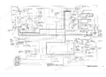
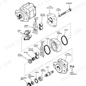
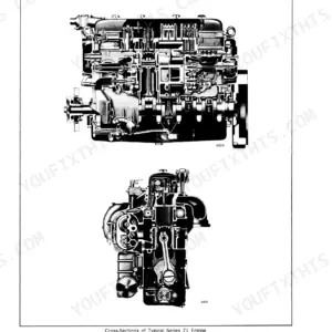
All 818 pages of this Case 888 Excavator Service Manual (OEM #8-66552) are dedicated to helping you tear down, troubleshoot, and rebuild your machine. Open the file to find complete hydraulic schematics tracing fluid through the high-pressure pump, full electrical wiring diagrams, and detailed turbocharger failure analysis. You get step-by-step removal procedures for the final drive transmission, swing motor, and track components, backed by massive torque tables for every fastener. Swap out the engine oil and hydraulic filters every 500 hours, then lock down the front cover bolts to exactly 18 lb-ft (24 Nm). Downtime drains your profits quickly. Grab this bookmarked download, pull the PDF up on your shop tablet, and get your excavator moving again.
What's Inside This Case 888 Manual
| System | Pages | Key Topics |
|---|---|---|
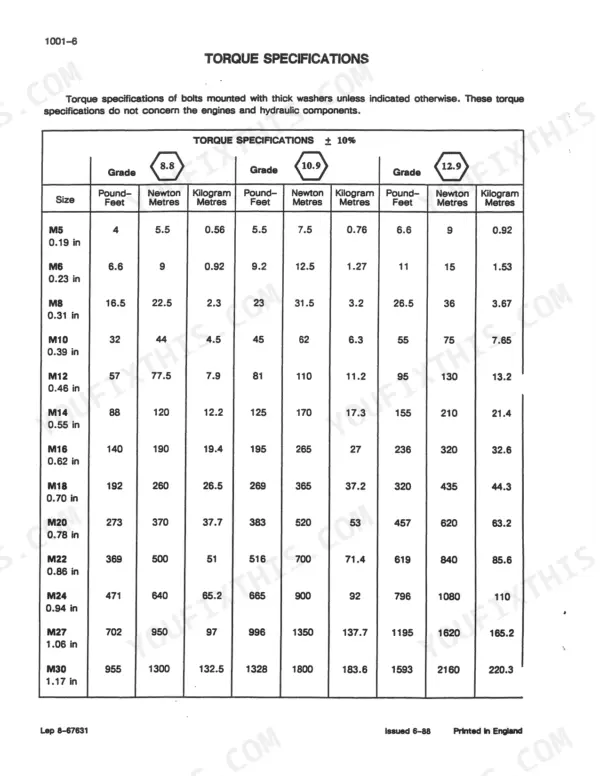
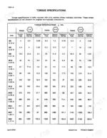
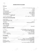
| Genreal | 5-44 | Safety Rules, General Information and Torque Specifications, General Engine Specifications, Detailed Engine Specifications, General Machine Specifications |
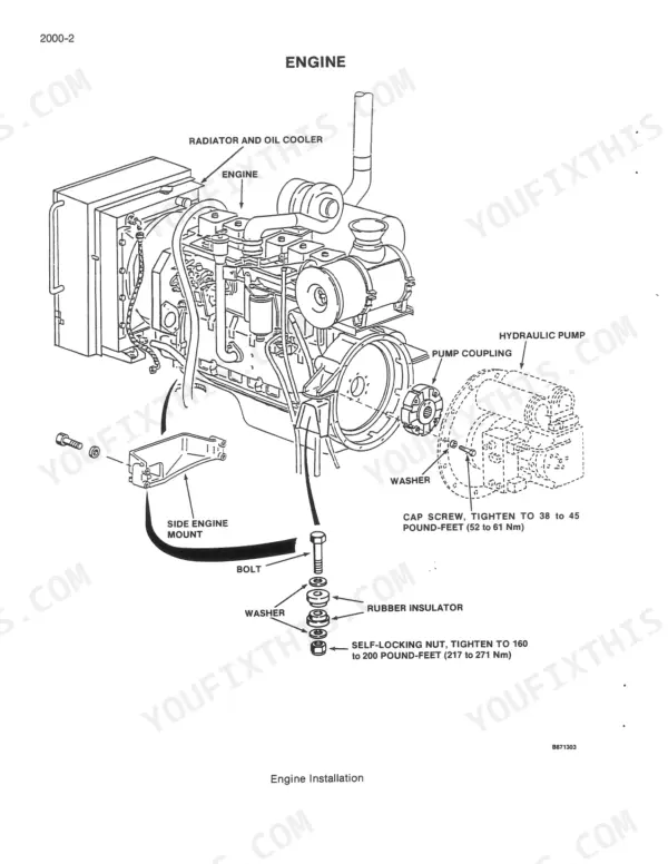
| Engine | 45-299 | Engine Removal and Installation and Radiator Removal and Installation, Engine Accessories, Cylinder Head and Valve Train, Cylinder Block, Pistons, Rods, Camshaft, Main Bearings |
| Fuel System | 300-373 | Fuel Lines, Fuel Tank, And Engine Controls, Fuel System and Filters, Fuel Injection Pump and Drive Gear, Fuel Injectors |
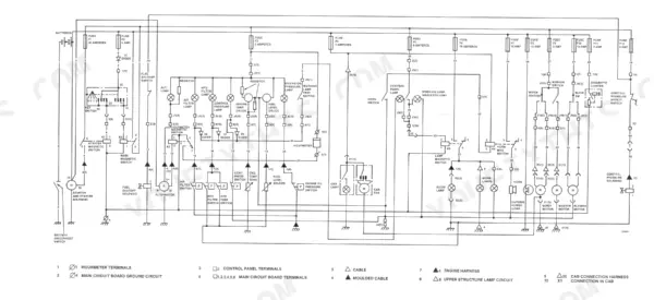
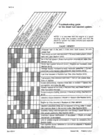
| Electrical | 374-436 | Removal and Installation of Electrical Components, Electrical Specifications and Troubleshooting, Electrical Schematic, Batteries, Starter and Starter Solenoid, Volt Alternator |
| Track | 437-470 | Removal and Installation of Track Components, Troubleshooting, Track Chain and Shoes, Track Rollers, Idler, And Sprocket |
| Power Train | 471-566 | Removal and Installation of Power Train Components, Maintenance, Drive and Swing Motor, Hydraulic Motor, Final Drive Transmission, Swing Transmission, Swing Drive Reduction |
| Hydraulics | 567-800 | Removal and Installation of Hydraulic Components, Maintenance and Service, Specifications and Troubleshooting, High Pressure Pump, Low Pressure Hydraulic Pump |
| Mounted Equipment | 801-814 | Boom, Arm, And Tool, Turntable Bearing and Related Parts |
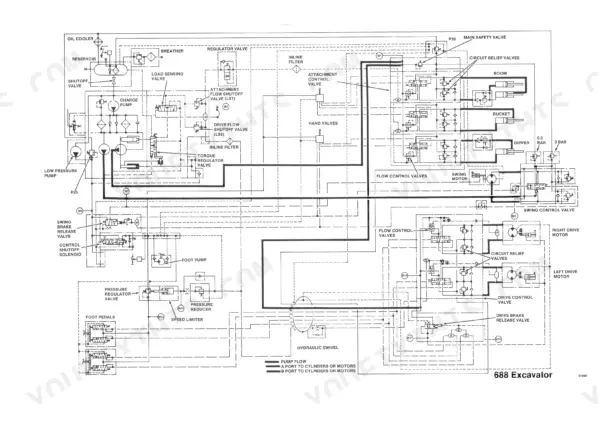
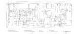
| Schematics | 815-818 | Electrical Schematics, Location Schematics, Hydraulic Schematics |
Quick Reference Specifications
| Specification | Value | Page |
|---|---|---|
| All Models | ||
| Engine Oil Filter Replacement Interval | Every 500 hours | p. 311 |
| Hydraulic Filter Replacement Interval | Every 500 hours | p. 598 |
| Front Cover Bolts Torque | 18 lb ft (24 Nm) (2.4 kgm) | p. 236 |
| Seal Carrier Bolts Torque | 7 lb ft (9 Nm) (0.9 kgm) | p. 155 |
| Fuse for Engine Temperature Gauge | 5 amperes | p. 381 |
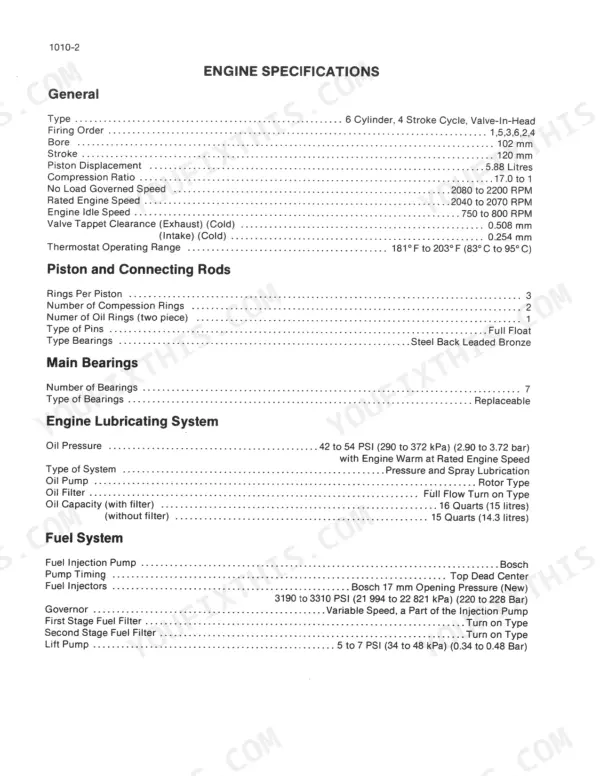
| Engine Oil Pressure (Warm, Rated Engine Speed) | 42 to 54 PSI (290 to 372 kPa) (2.90 to 3.72 bar) | p. 14 |
| Engine Bore | 102 mm | p. 14 |
| Engine Stroke | 120 mm | p. 14 |
| Piston Displacement | 5.88 Litres | p. 14 |
| Engine Oil Capacity (with filter) | 16 Quarts | p. 14 |
| 6T-590 and 6TA-590 Engine | ||
| Fuel Shutoff Solenoid Torque (6T-590 and 6TA-590 Engine) | 32 lb ft (43 Nm) (4.3 kgm) | p. 316 |
| 6-590 Engine | ||
| Fuel Shutoff Solenoid Torque, 6-590 Engine | 10 lb ft (15 Nm) (1.5 kgm) | p. 316 |
Case 888 Common Problems This Manual Covers
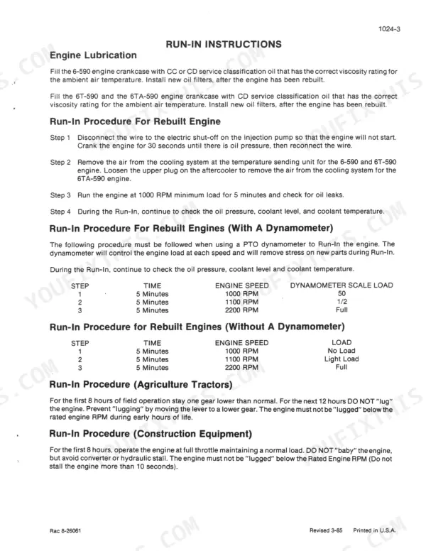
Case 888 excavator oil leaks appear at crankcase seals shortly after engine run-in at 1000 RPM
Inspect the seal carrier and front cover for improper seating before blaming the gasket itself. Torque the seal carrier bolts to 7 lb ft (9 Nm) as specified on page 155, and confirm the filter head bolts on page 236 are set to 18 lb ft (24 Nm). Wipe the area dry, run the engine, and recheck for weeping after 30 minutes.
Manual Section: Engine p. 155Loss of oil pressure immediately after cold start, gauge reads near zero
Verify the engine was properly primed before cranking; skipping prime causes a momentary zero reading that mechanics mistake for pump failure. Once running, confirm pressure at warm rated speed falls between 42 to 54 PSI (290 to 372 kPa) per the spec on page 14. Pull the new oil filter and check the gasket seated flush and was hand-tightened, not overtorqued.
Manual Section: Engine p. 14Hydraulic system acts erratic or shuts down with E02 coolant temperature high code displayed
Bleed the cooling system at the highest point first; trapped air trips the temperature sending unit before the engine actually overheats. Check the sending unit circuit against the 5 ampere fuse on page 381. If the code persists, drain and inspect the hydraulic reservoir (26.4 U.S. gallon capacity, page 30) and swap the filter, serviced every 500 hours per page 598.
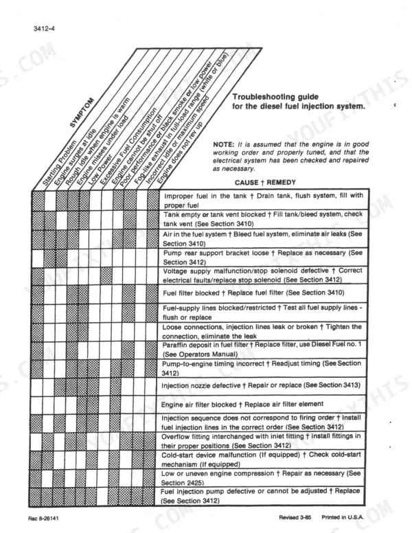
Manual Section: Hydraulics Specifications and Troubleshooting p. 598Engine shuts off unexpectedly with E04 injection pump shut-off wire fault code
Trace the electric shut-off wire at the injection pump for a loose pin or corroded connector before swapping the solenoid outright. On 6T-590 and 6TA-590 engines, torque the fuel shutoff solenoid to 32 lb ft (43 Nm) per page 316. Clear the E04 code, cycle the key, and if the fault returns immediately, replace the harness section feeding the solenoid.
Manual Section: Diesel Fuel Injection System Troubleshooting Guide p. 316Starter cranks slowly or fails to engage entirely during cold weather starts
Load-test each battery and clean the terminals before condemning the starter motor. Follow the wiring path from the starter solenoid documented in the electrical section starting page 374, checking for voltage drop past the main relay. In freezing temperatures, warm the engine oil or run a block heater first, since thickened oil is the most common cause of a slow crank.
Manual Section: Electrical Specifications and Troubleshooting p. 374Track slides off the drive sprocket and needs frequent tension adjustments during operation
Measure track sag against the tension chart before pumping more grease into the adjuster cylinder. Torque the track shoe mounting bolts to 200 pound-feet (270 Nm) as specified on page 450. Check idler and sprocket alignment for worn teeth that let the chain climb under load, then regrease the tensioner fitting and recheck sag after a short run.
Manual Section: Track Troubleshooting p. 450Frequently Asked Questions
What is the torque specification for the main frame pivot bolts on Case 888?
For components mounted to the main frame, the cap screws for the turntable bearing should be tightened to 450 to 540 pound-feet (610 to 730 Nm). General torque specifications for bolts are also provided by size and grade in the manual. p. 810
What is the engine oil capacity for the Case 888 Excavator?
The engine oil capacity for the Case 888 Excavator is 16 U.S. quarts (15 litres) when the filter is included, and 15 U.S. quarts (14.3 litres) without the filter. p. 14
What are the cold valve tappet clearances for the Case 888 Excavator engine?
The cold valve tappet clearance for the exhaust valves is 0.508 mm, and for the intake valves is 0.254 mm. p. 14
What is the recommended replacement interval for the fuel filters on the Case 888 Excavator?
The fuel filters (first and second stage) should be replaced every 500 hours of operation or whenever there is a loss of engine power. p. 311
What format is this Case 888 manual in?
This is a 818-page searchable PDF ready for immediate download. Works on any device, so pull it up on your phone while you're under the hood. No shipping, no waiting.
Can I print this Case 888 manual?
Yes. Print the sections you need to take out to the shop for your own use. Standard letter or A4 paper works.
Are wiring diagrams part of this Case 888 Service Manual?
Yes, this Case 888, 888 Excavator Service Manual includes complete electrical wiring diagrams, wire routing, and connector pinouts.









Reviews
There are no reviews yet.