
Part of the Case Repair Manuals.
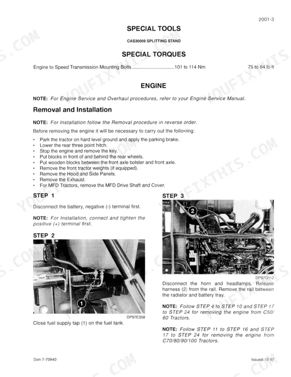
Written for six Case tractors in the C50 to C100 series, 2WD and MFD alike, this 407-page Case C50 to C100 series service manual PDF (part number 7-70900) is the factory shop book. Transmission work fills the largest share of the book: engine clutch, splitting the tractor, range, speed and powershift transmissions, rear axle, differential, and standard and shiftable PTO. Electrical faults get traced on wiring schematics with fuse, relay and connector identification, and the hydraulic schematic leads into hitch adjustments plus multi control valve, pump and flow control valve service. Plan on 358 kg (789 lb) dry when you lift a C50 or C60 engine, and run the engine to speed transmission bolts to 107 to 114 Nm (75 to 84 lb ft) on reassembly. A guessed clevis torque can let go mid-field. Your bookmarked PDF searches on screen, and any section prints clean for the bench, where oily thumbprints matter less than the weather.
What's Inside This Case C50–C100 Series Manual
| System | Pages | Key Topics |
|---|---|---|
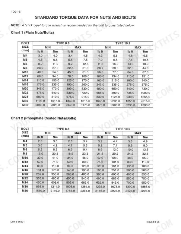
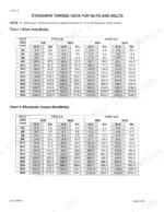
| General | 2-21 | Safety Rules, General Information, Standard Torque Data |
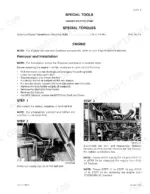
| Removal and Installation | 22-29 | Engine Removal and Installation |
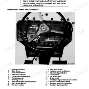
| Electrical | 30-111 | Schematic Symbols and Legends, Instrument Panel Switches, Fuse and Relay Identification, Electrical Connectors |
| Steering | 112-125 | Steering Hand Pump, Steering Cylinder - 2WD Tractors, Front Axle - 2WD Tractors |
| Steering Cylinder | 126-143 | Steering Cylinder Pivot Bushings, Front Axle, Track Adjustment |
| Transmission | 144-295 | Engine Clutch, Separating the Tractor, Range Transmission Removal, Speed Transmission Removal, Speed Transmission Servicing, Powershift Transmission |
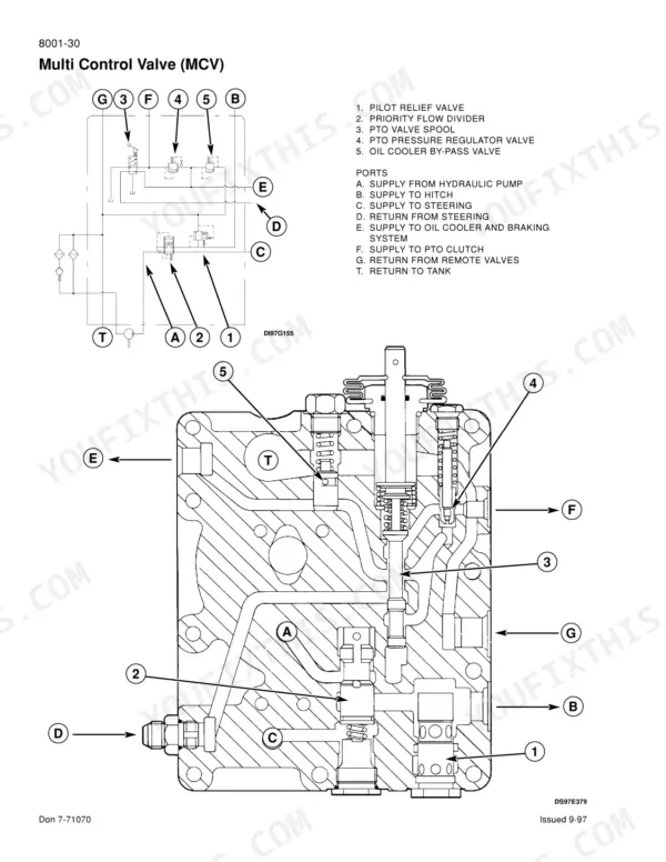
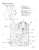
| Hydraulics | 296-383 | Hydraulic Troubleshooting and Schematic, Hydraulic Hitch Adjustments, Multi Control Valve and Hydraulic Pump, Unloading and Flow Control Valve, Hydraulic Housing Servicing |
| Chassis and Mounted Equipment | 384-407 | Hand and Foot Throttle Adjustment, Foot Brake Adjustment, Clutch Pedal Adjustment, Parking Brake Adjustment |
Quick Reference Specifications
| Specification | Value | Page |
|---|---|---|
| C50 and C60 Tractors | ||
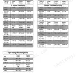
| Threaded spacer (1) torque | 15 Nm (11 lbft) | p. 28 |
| C50 and C60 | ||
| Engine dry weight | 358 kg (789 lb) | p. 28 |
| All Models | ||
| Clevis pin retaining bolt torque | 27 to 31 Nm (20 to 23 lb ft) | p. 131 |
| Lower bushing carrier retaining bolts torque | 110 to 122 Nm (80 to 90 lb ft) | p. 131 |
| Piston rod clevis torque | 110 to 135 Nm (80 to 100 lb ft) | p. 133 |
| PTO Clutch Access Cover Torque | 117 to 133 Nm (86 to 98 lb ft) | p. 276 |
| PTO Shaft Cover Retaining Bolts Torque | 45 to 50 Nm (33 to 37 lb ft) | p. 276 |
| Pump efficiency | not less than 80% | p. 306 |
| Hydraulic Filter Retaining Bolt Torque | 16 to 21 Nm (12 to 16 lb ft) | p. 350 |
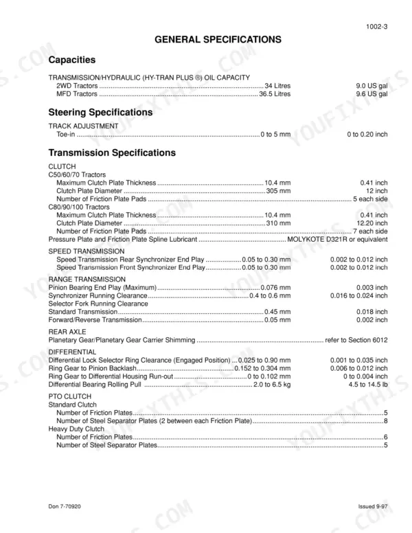
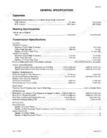
| Transmission/Hydraulic Oil Capacity (2WD Tractors) | 34 Litres | p. 14 |
| Transmission/Hydraulic Oil Capacity (MFD Tractors) | 36.5 Litres | p. 14 |
| Steering Relief Valve Pressure | 141 to 148 bar | p. 15 |
Case C50–C100 Series Common Problems This Manual Covers
Engine clutch friction plate pads blue or cracked between rivets at clutch inspection
Inspect the friction plate before you spend money on parts: blue pads do not mean excess heat, and flaking or cracking between rivets is normal (page 147). Do not reface the pressure plate. Torque flywheel bolts to 105 Nm (page 17), and lubricate the friction plate and pressure plate splines with MOLYKOTE D321R before joining engine to transmission (page 28).
Manual Section: Engine Clutch Troubleshooting p. 147Starter and neutral start circuit check, engine will not crank at the key switch
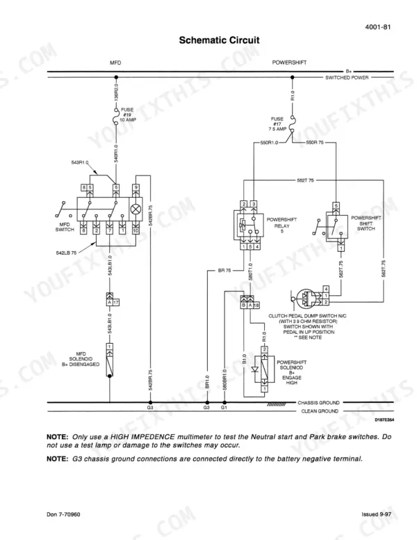
Park on hard level ground with the parking brake on, engine off and rear wheels blocked. Check that the battery is fully charged and every connection is clean and tight, then trace the starter and neutral start circuit with a high impedance multimeter, never a test lamp (page 32). If the battery electrolyte is frozen, do not charge or jump start it; it can explode (page 7).
Manual Section: Electrical Troubleshooting p. 32PTO pressure test and linkage adjustment check when the PTO shaft will not engage
Check the PTO linkage adjustment following page 393: park on hard level ground, apply the parking brake, stop the engine, remove the key and put blocks in front of and behind the front wheels. Test PTO pressure under Hydraulic System Diagnostic Testing. If you open the PTO clutch access cover, torque its bolts to 117 to 133 Nm (page 276) and get back in the field.
Manual Section: PTO Linkage Adjustment p. 393Frequently Asked Questions
How do you fix case C50 to C100 tractor rear hitch and remote valves slow to lift under load?
Run the pump efficiency test on page 306; efficiency must not be less than 80%. Then check main relief valve pressure against 172 bar (2494 psi) on page 308. Follow both procedures exactly as written, as page 6 warns, and keep everyone clear when cycling cylinders. Check for leaks with cardboard or wood, never your hand (page 7). p. 306
How do you fix steering hand pump relief valve pressure reading outside spec during hydraulic diagnostic test?
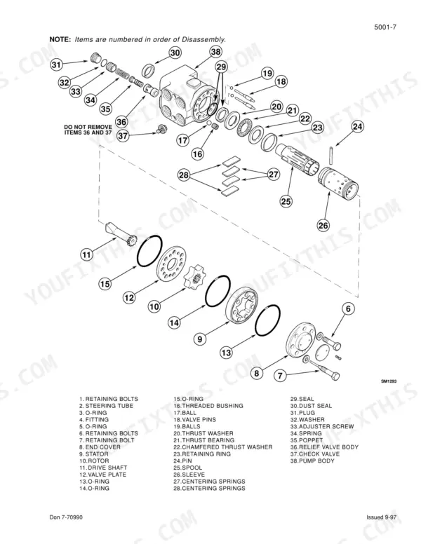
Test steering relief valve pressure and set it to 141 to 148 bar, per page 15. Leave the hood and side panels off until the valve is set (page 115). When servicing the hand pump, never remove the relief valve body or check valve, and never use a magnet on the balls (page 117). p. 15
How do you fix transmission drive pressure low when selecting forward or reverse, tractor weak in one direction?
Test drive pressure following page 314: select reverse, then forward, and record the gauge reading for each direction. Pressure must be 22 bar (320 psi). Do not turn the steering wheel during this test. If the reading is off, work through the possible causes listed with the test before you split the tractor. p. 314
What format is this Case C50–C100 Series manual in?
Instant PDF download. You get the full 407-page searchable Service Manual immediately after payment. Open it on your laptop, tablet, or phone right in the shop.
Can I print specific sections of this Case C50–C100 Series Service Manual?
Yes. Print individual pages or full chapters for your own shop use, on letter or A4 paper.
Is there a wiring diagram in this Case C50–C100 Series Service Manual?
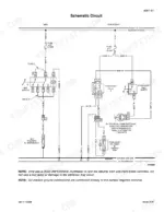
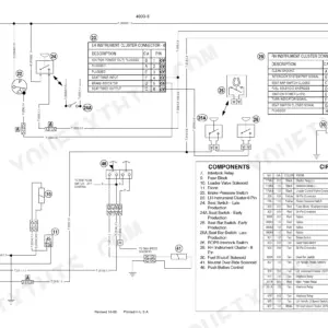
Yes. The Electrical section of this Case C50–C100 Series Service Manual includes a schematic circuit diagram on page 110, alongside schematic symbols and legends.




Reviews
There are no reviews yet.