
Part of the Case Repair Manuals.
Engine internals on the Yanmar 3TNV88F-ESHYB are covered: cylinder heads, valve clearance, connecting rods and pistons, crankshaft and flywheel, plus the fuel injection pump with fuel injector pressure and the injection timing method. The torque figures for the cylinder head, connecting rod and main bearing cap bolts are printed in the engine section.
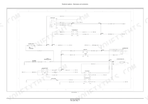
The book then covers the variable displacement pump, the main control valve and its relief valves, and the pilot circuit. Swing and travel motors, the central joint and the undercarriage idler wear limits follow, then electrical schematic sheets 01-15 and the SPN-FMI fault code index.
The manual is Case part number 48127449 and covers both the cab and canopy CX37C with the Tier IV final engine. Each system has its own section, so you can go straight to the travel motor charts or the alternator test.
What's Inside This Case CX37C Manual
| System | Pages | Key Topics |
|---|---|---|
| Introduction and Machine Data | 1-50 | Safety Rules, Standard and Special Torque Settings, Machine Specifications, Weights, Dimensions, Working Range, Conversion Tables, Fluids and Lubricants, Product Identification |
| Engine and Crankcase | 51-107 | Engine Diagnosis, Service Limits, Compression Pressure Measurement, Engine Torque for Special Use, Engine Troubleshooting Chart, Crankcase |
| Valve Drive, Cylinder Head, Pistons and Crankshaft | 108-157 | Valve Drive and Gears, Cylinder Heads and Valve Clearance, Connecting Rods and Pistons, Crankshaft and Flywheel |
| Fuel System, Air Intake and EGR | 158-217 | Fuel Tanks, Fuel Filters, Fuel Injection System with Injector Pressure and Injection Timing, Air Cleaners, Exhaust Gas Recirculation |
| Engine Cooling and Lubrication | 218-254 | Engine Cooling System, Fan and Drive, Engine Lubrication System |
| Hydraulic System Overview | 255-303 | Hydraulic Circuit Description, Hydraulic Schematic, Releasing Pressure, Hydraulic Troubleshooting |
| Variable Displacement Pump | 304-337 | Main Pump, System Pressure Regulator Relief Setting, Pump Troubleshooting |
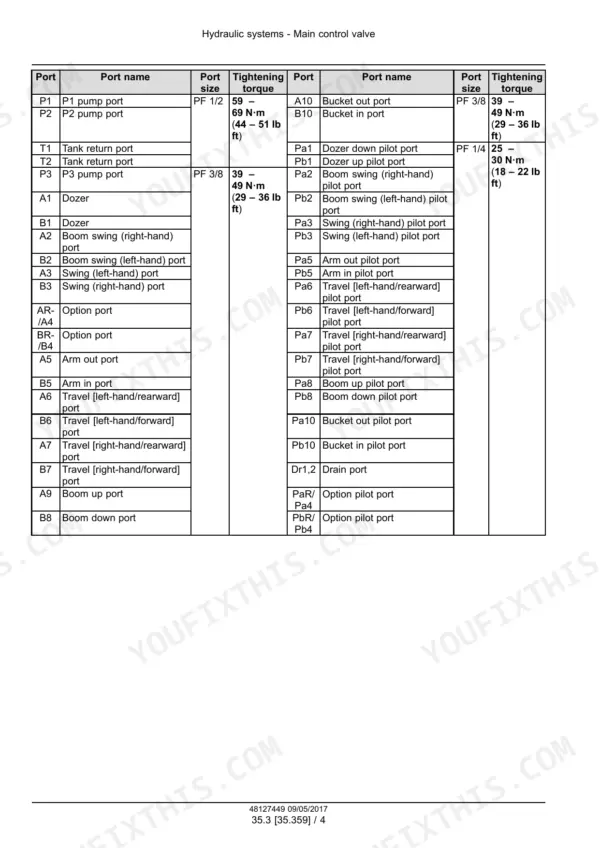
| Main Control Valve | 338-389 | Main Control Valve Ports and Tightening Torques, Main and Overload Relief Valves, Troubleshooting |
| Pilot System and Hand and Foot Controls | 390-465 | Pilot System, Hydraulic Hand Control, Hydraulic Foot Control |
| Hydraulic Swing System | 466-515 | Swing Motor and Swing Reduction Gear, Swing Troubleshooting |
| Hydraulic Travel System and Central Joint | 516-599 | Travel Motor and Reduction Unit, Travel Motor Troubleshooting, Hydraulic Central Joint |
| Boom, Dipper, Bucket, Swing Arm and Dozer Hydraulics | 600-676 | Boom Hydraulic System Troubleshooting, Dipper and Bucket Hydraulics, Swing Arm Hydraulics, Dozer Blade Cylinders, Hydraulic Lines |
| Frames and Ballasting | 677-686 | Ballasts and Supports |
| Tracks and Track Suspension | 687-732 | Track Frame and Driving Wheels, Tracks, Track Tension Units and Service Limits, Track Rollers |
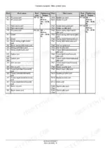
| Electrical System | 733-793 | Electrical Component Identification, Electrical System Layout, Engine Diagnostic Connector |
| Harnesses, Connectors and Electrical Schematic Sheets | 794-939 | Electrical Schematic Sheets 01-15 (Power Distribution, Grounding, Engine Controller), Connectors, Harness Routing |
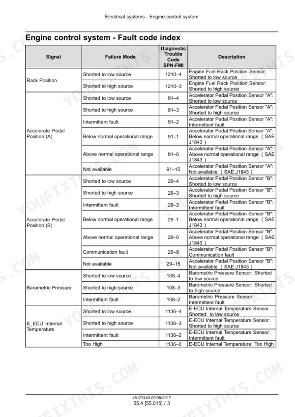
| Cab Engine Controls and Engine Control System | 940-957 | Speed Control Switch, Engine Control System, Engine Fault Code Index (Spn-Fmi) |
| Starting System, Alternator and Battery | 958-1007 | Engine Starter, Alternator and Battery Testing and Troubleshooting |
| Engine Sensors, Cab Controls, Wipers, Lighting and Warnings | 1008-1080 | Fuel Tank System, Intake and Exhaust, Cooling and Oil System Sensors, Instrument Cluster, Cab Controls, Lever Lock Solenoid, Wiper and Washer, External and Cab Lighting, Warning Indicators |
| Booms, Dippers, and Buckets | 1081-1118 | Boom Pivoting Support, Boom, Dipper Arm, Bucket |
| Platform, Cab, Bodywork, and Decals | 1119-1137 | Engine Hood and Panels, Machine Shields and Guards |
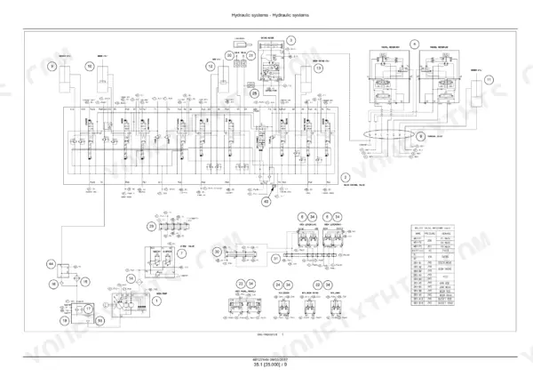
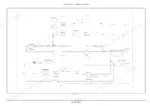
| Fold-Out Electrical and Hydraulic Schematics | 1138-1140 | Electrical Schematic CX33C-CX37C 48125605EN, Hydraulic Schematic CX33C-CX37C 48125599EN |
Quick Reference Specifications
| Specification | Value | Page |
|---|---|---|
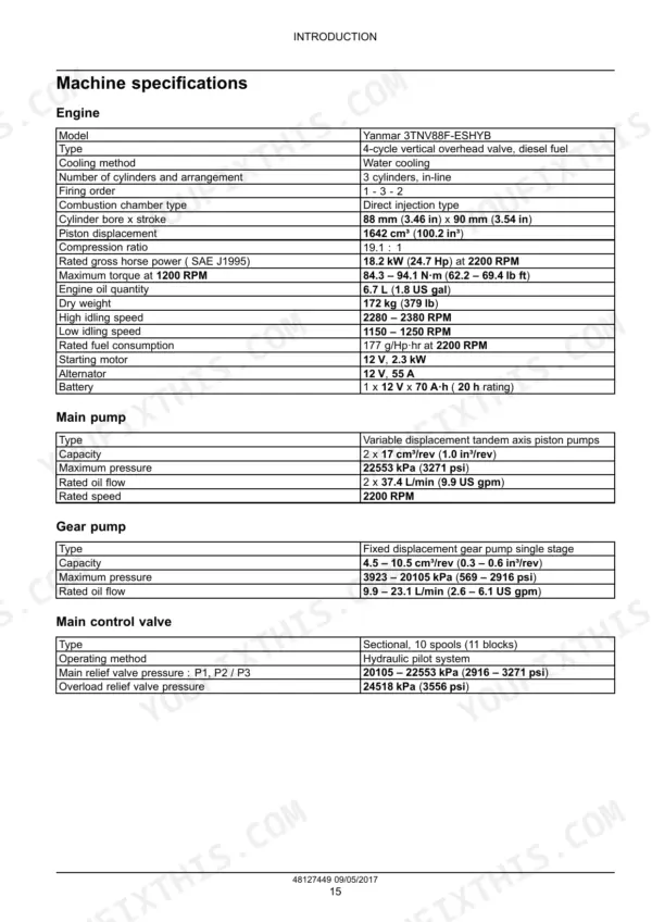
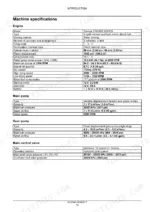
| Engine | Yanmar 3TNV88F-ESHYB | p. 20 |
| Engine type | 3 cylinders, in-line, 4-cycle vertical overhead valve, diesel fuel | p. 20 |
| Piston displacement | 1642 cm³ (100.2 in³) | p. 20 |
| Rated gross horse power (SAE J1995) | 18.2 kW (24.7 Hp) at 2200 RPM | p. 20 |
| Main pump | Variable displacement tandem axis piston pumps, 2 x 37.4 L/min (9.9 US gpm) | p. 20 |
| Main relief valve pressure P1, P2 / P3 | 20105 - 22553 kPa (2916 - 3271 psi) | p. 20 |
| Overload relief valve pressure | 24518 kPa (3556 psi) | p. 20 |
| Swing / travel motor relief pressure | 19616 kPa (2845 psi) swing / 22553 kPa (3271 psi) travel | p. 21 |
| Operating weight (cab / canopy version) | 3760 kg (8289 lb) cab / 3620 kg (7981 lb) canopy | p. 23 |
| Fuel tank | 40 L (10.6 US gal) | p. 42 |
| Engine oil | 6.7 L (1.8 US gal), SAE 15W-40 | p. 42 |
| Engine coolant | 5 L (1.3 US gal) | p. 42 |
| Hydraulic oil tank | 37 L (9.8 US gal) | p. 42 |
| Hydraulic system total capacity | 60 L (15.9 US gal) | p. 42 |
| Travel reduction unit oil | 0.5 L (0.13 US gal) x2, SAE 80W90 | p. 42 |
| Intake/exhaust valve clearance | 0.150 - 0.250 mm (0.006 - 0.010 in) | p. 65 |
| Compression pressure at 250 RPM | 3.33 - 3.53 MPa (483.02 - 512.03 psi), limit 2.65 - 2.85 MPa (384.38 - 413.39 psi) | p. 65 |
| Cylinder head bolt torque (M10 × 1.25) | 85.3 - 91.1 N·m (63 - 67 lb ft) | p. 64 |
| Main bearing cap bolt torque (M12 × 1.5) | 93.2 - 98.1 N·m (69 - 72 lb ft) | p. 64 |
| Main control valve P1/P2 port torque (PF 1/2) | 59 - 69 N·m (44 - 51 lb ft) | p. 341 |
Case CX37C Common Problems This Manual Covers
Travel does not function at all in one direction
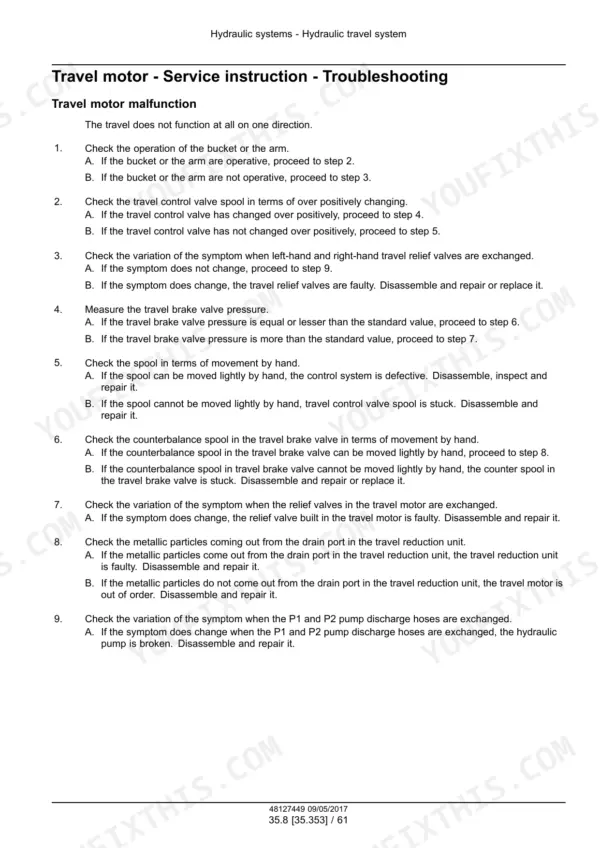
Use the branching chart on page 576. It starts by checking whether the bucket or arm works. If it does, the chart checks that the travel control valve spool changes over, then the travel brake valve pressure, the counterbalance spool or the relief valves in the travel motor, and finally the travel reduction unit drain port for metallic particles. If the bucket and arm do not work either, it swaps the left-hand and right-hand travel relief valves and then the P1 and P2 pump discharge hoses.
Manual Section: Hydraulic travel system and central joint p. 576Boom or arm actions impossible
Use the branching chart on page 605. It starts with the left-hand and right-hand travel motors. If they work, check the other attachments, then the main control valve or gear pump pilot pressure, the port relief valve, the pilot piping, gear pump delivery and spool movement by hand. If the travel motors do not work either, check the hydraulic oil tank level, then remove the dust plug under the engine flywheel and look for coupling element particles, and then disassemble the main relief valve.
Manual Section: Boom, dipper, bucket, swing arm and dozer hydraulics p. 605Battery indicator stays on or flashes
Page 995 calls for a fully charged battery and a 0 V - 30 V DC voltmeter, 0,5 class. Indicator on at idle: inspect or replace the fan belt and inspect the alternator. Flashing: inspect the diode positive side. At 1500 RPM, a battery voltage greater than 15.5 V means replace the regulator.
Manual Section: Starting system, alternator and battery p. 995Compression below the limit value
The standard at 250 RPM is 3.33 - 3.53 MPa (483.02 - 512.03 psi), and the limit is 2.65 - 2.85 MPa (384.38 - 413.39 psi) (page 65). Below the limit, page 75 lists the causes in this order: air cleaner element, valve clearance, valve timing and cylinder head gasket. The list continues with the valve and valve seat, then the piston and piston rings.
Manual Section: Engine and crankcase p. 75Frequently Asked Questions
What does a Case CX37C engine fault code mean?
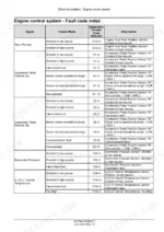
Codes are listed as SPN-FMI pairs with the signal, failure mode and description on pages 948-950. For example, 110-4 is Engine Coolant Temperature Sensor shorted to low source and 110-0 is Engine Coolant Temperature too high. 91-4 is Accelerator Pedal Position Sensor A shorted to low source, 638-4 is Engine Fuel Rack Actuator shorted to low source, and 158-1 is System Voltage too low. The index gives the code and its description only. It does not give repair steps. p. 948
What are the torque specs on the CX37C engine and control valve?
Page 64 lists the cylinder head bolt M10 x 1.25 at 85.3 - 91.1 N·m (63 - 67 lb ft) and the connecting rod bolt M9 x 1.0 at 44.1 - 49.0 N·m (33 - 36 lb ft). The main bearing cap bolt M12 x 1.5 is 93.2 - 98.1 N·m (69 - 72 lb ft). On the main control valve (page 341), the P1 and P2 pump ports (PF 1/2) take 59 - 69 N·m (44 - 51 lb ft). PF 3/8 ports take 39 - 49 N·m (29 - 36 lb ft), and PF 1/4 pilot ports take 25 - 30 N·m (18 - 22 lb ft). p. 64
What are the CX37C fluid capacities?
Page 42 lists the fuel tank at 40 L (10.6 US gal) and engine oil at 6.7 L (1.8 US gal) SAE 15W-40. The travel reduction units take 0.5 L (0.13 US gal) x2, SAE 80W90, and engine coolant is 5 L (1.3 US gal). The hydraulic oil tank holds 37 L (9.8 US gal). Total hydraulic system capacity is 60 L (15.9 US gal). p. 42
What fuel injector pressure and injection timing does the Case CX37C Yanmar 3TNV88F engine use?
Fuel injector pressure depends on the identification mark (page 173). W is 19.6 - 20.6 MPa (2843 - 2988 psi), V is 21.6 - 22.6 MPa (3133 - 3278 psi), S is 18.6 - 19.6 MPa (2697 - 2843 psi) and R is 21.1 - 22.1 MPa (3060 - 3205 psi). Set a new injector, or one disassembled for service, 0.5 MPa (72.5 psi) higher than standard. For timing, page 178 gives a formula: (timing index number x 2) + FIR number = injection timing in degrees. The index number is stamped on the pump housing, and the FIR number is on the engine data sheet. p. 173
How do I check valve clearance, and where does the diagnostic tool plug in?
Check the intake and exhaust valves with that cylinder's piston at TDC on the compression stroke (page 140). The standard clearance is 0.150 - 0.250 mm (0.006 - 0.010 in) (page 65). For the engine diagnostic service tool, open the door under the operator's seat and connect the tool to connector CN-148 (page 792). p. 140









Reviews
There are no reviews yet.