
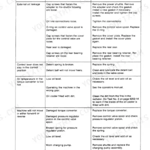
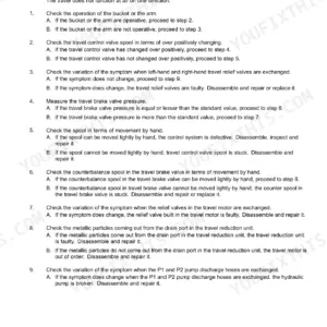
Part of the Case Repair Manuals.
Test No. 1 on the 1835B Uni-Loader hydrostatic drive reads charge pressure, and Test No. 2 checks charging pump output. If charge pressure was as specified, the book says do Test No. 3 (page 650). After those tests come the piston pump and hydrostatic motor overhaul, the neutral adjustment, and the drive chains and axle housings.
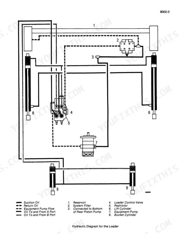
The book covers both engine options for this machine, the 188 diesel and the 148 spark ignition gasoline engine. Maintenance steps are split into If equipped with diesel engine and If equipped with gasoline engine. It also covers the diesel fuel system with Roosa Master injectors, the carburetor, and the wiring diagrams. Loader, auxiliary and backhoe hydraulic diagrams come with the relief valve tests.
When it's just you and the loader in the yard with nobody to call, the numbers are on the page. Keep it on a tablet in the truck or printed in the shop, wherever the machine is working.
What's Inside This Case 1835B Manual
| System | Pages | Key Topics |
|---|---|---|
| General | 1-11 | Table of Contents, Safety Rules, Service Manual Introduction, Product Identification and Serial Numbers, Standard Torque Specifications |
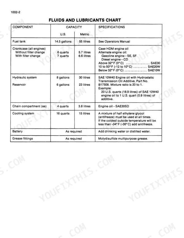
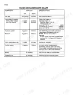
| Maintenance and Lubrication | 12-14 | Fluids and Lubricants Chart, Maintenance Chart and Service Intervals |
| 188 Diesel Engine Specifications | 15-28 | General and Detailed Engine Specifications, Special Torques for the 188 Diesel Engine |
| 148 Spark Ignition Engine Specifications | 29-40 | General and Detailed Engine Specifications, Special Torques for the 148 Spark Ignition (Gasoline) Engine |
| Engine Removal and Accessories | 41-80 | Engine Removal and Installation, Air Cleaner, Muffler, Ether Injection System, Radiator |
| 188 Diesel Engine Diagnosis and Tune-Up | 81-124 | Engine Diagnosis (Fuel, Compression, Combustion), Engine Tune-Up, Engine Hard to Start or Will Not Start, Engine Misfires, Engine Overheats, Engine Lacks Power |
| 188 Diesel Cylinder Head and Valve Train | 125-186 | Cylinder Head, Valve Train and Camshaft |
| 188 Diesel Block, Crankshaft, Oil Pump and Cooling | 187-260 | Cylinder Block, Sleeves, Pistons and Rods, Crankshaft, Main Bearings, Flywheel, Oil Seals, Oil Pump, Thermostat and Water Pump |
| 148 Spark Ignition Engine Tune-Up | 261-298 | Engine Tune-Up for the 148 Spark Ignition Engine, Governor Linkage Adjustments, Checking the Engine Compression, Locating Top Dead Center, Replacing the Distributor Points and Condenser |
| 148 Spark Ignition Cylinder Head and Valve Train | 299-358 | Cylinder Head, Valve Train and Camshaft for the 148 Engine |
| 148 Spark Ignition Block, Crankshaft, Lubrication and Cooling | 359-448 | Cylinder Block, Sleeves, Pistons and Rods, Crankshaft, Main Bearings, Flywheel, Oil Pan, Oil Pump, Water Pump and Fan Belt; Diesel Engine Lubrication (Section 2555) |
| Diesel Fuel System | 449-512 | Throttle Adjustments, Fuel Tank and Lines, Fuel Filters, Fuel Injection Pump, Roosa Master Fuel Injectors |
| Carburetor | 513-536 | Model 68 X 7 Zenith Carburetor for the Gasoline Engine, Removal of Carburetor, Check Operation of Fuel Shutoff Solenoid, Float Level, Cleaning and Inspection |
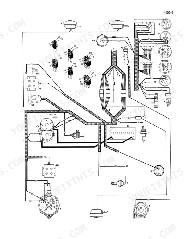
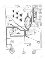
| Electrical Troubleshooting and Wiring Diagrams | 537-556 | Electrical System Specifications, Troubleshooting Chart, Charging and Starting Circuit Tests, Wiring Diagrams for Diesel and Gasoline Engines |
| Electrical Components | 557-648 | Fuel Gauge and Warning Lamps, Batteries, Starter, Alternator, Distributor Ignition System |
| Hydrostatic Troubleshooting and Diagrams | 649-663 | Hydrostatic System Troubleshooting Tests (Charge Pressure, Charging Pump Output, Circuit Relief Valve), Hydrostatic System Diagrams and Operation |
| Piston Pump and Hydrostatic Motor | 664-763 | Piston Pump and Hydrostatic Motor Removal, Overhaul and Installation |
| Hydrostatic Controls and Drive | 764-832 | Hydrostatic Controls and Neutral Adjustment, Drive Sprockets, Chains and Axle Housings, Drive Coupling, Wheels and Tires |
| Brakes | 833-836 | Parking Latch |
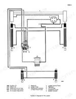
| Hydraulic Specifications, Diagrams and Tests | 837-873 | Hydraulic System Specifications, Hydraulic Diagrams for Loader, Auxiliary and Backhoe Circuits, Troubleshooting, Pressure Checks, Flowmeter Tests, Relief Valve Tests, Cleaning the Hydraulic System |
| Pumps, Control Valves and Cylinders | 874-980 | Equipment and Charge Pump, Loader Control Valve, Auxiliary Control Valve, Backhoe Control Valve, Cylinders |
| Mounted Equipment | 981-1038 | Loader, Backhoe, ROPS Canopy, Operators Seat, Decals, Painting and Noise Control |
Quick Reference Specifications
| Specification | Value | Page |
|---|---|---|
| 188 diesel | ||
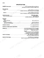
| Engine option: Case 188 diesel | 188 Cubic Inches (3 081 cm3), Case Open Chamber, 4 Cylinder, 4 Stroke Cycle, Valve-in-Head; Roosa-Master injection pump, timing 4 Degrees Before Top Center | p. 16 |
| Engine speeds, 188 diesel (rated / no load / idle) | 2100 RPM rated; 2285 to 2315 RPM no load; 825 to 875 RPM idle | p. 16 |
| Valve tappet clearance (cold), 188 diesel | 0.014 Inch (0.356 mm) exhaust; 0.012 Inch (0.305 mm) intake | p. 16 |
| 148 spark ignition | ||
| Engine option: 148 spark ignition (gasoline) | 148 Cubic Inches (2 425 cm3), 4 Cylinder, 4 Stroke Cycle, Valve-in-Head; ignition timing static 1 Degree BTC, running 35 Degrees BTC at rated engine speed | p. 30 |
| Engine speeds, 148 spark ignition (rated / no load / idle) | 2100 RPM rated; 2295 to 2325 RPM no load; 775 to 825 RPM idle | p. 30 |
| Valve tappet clearance (cold), 148 spark ignition | 0.014 Inch (0.356 mm) intake; 0.020 Inch (0.508 mm) exhaust | p. 30 |
| All Models | ||
| Fuel tank | 14.5 gallons (55 litres) | p. 12 |
| Crankcase (all engines) | 6 quarts (5.7 litres) without filter change; 7 quarts (6.6 litres) with filter change; Case HDM engine oil | p. 12 |
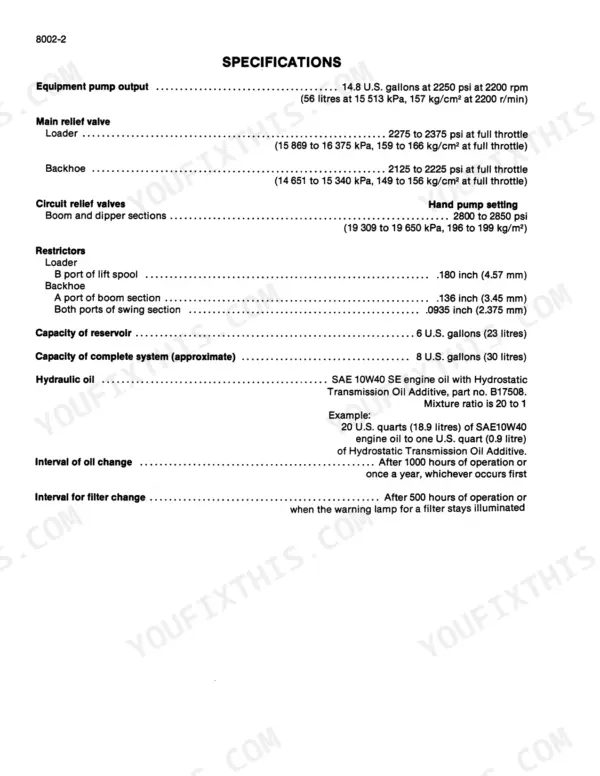
| Hydraulic system | 8 gallons (30 litres); reservoir 6 gallons (23 litres); SAE 10W40 engine oil with Hydrostatic Transmission Oil Additive B17508, 20 to 1 | p. 12 |
| Chain compartment (each) | 4 quarts (3.8 litres), engine oil SAE30SD | p. 12 |
| Cooling system | 16 quarts (15 litres) | p. 12 |
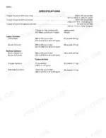
| Wheel nuts | 80 to 90 pound-feet (108 to 122 N m) | p. 13 |
| Equipment pump output | 14.8 U.S. gallons at 2250 psi at 2200 rpm (56 litres at 15513 kPa) | p. 838 |
| Main relief valve | 2275 to 2375 psi at full throttle (15869 to 16375 kPa) (Loader) / 2125 to 2225 psi at full throttle (14651 to 15340 kPa) (Backhoe) | p. 838 |
| Circuit relief valves, boom and dipper (hand pump) | 2800 to 2850 psi (19309 to 19650 kPa) | p. 838 |
| Charging pump | 15 U.S. gpm at 150 psi at 2200 rpm | p. 874 |
| Charge pressure (Test No. 1) | Not less than 150 psi (1034 kPa), oil at operating temperature | p. 650 |
| Drive chain deflection | Not more than 3/4 to one inch (19 to 25 mm) at any point | p. 769 |
| Axle housing self-locking nuts | 90 to 100 pound-feet (122 to 135 N m) | p. 769 |
| Loader | ||
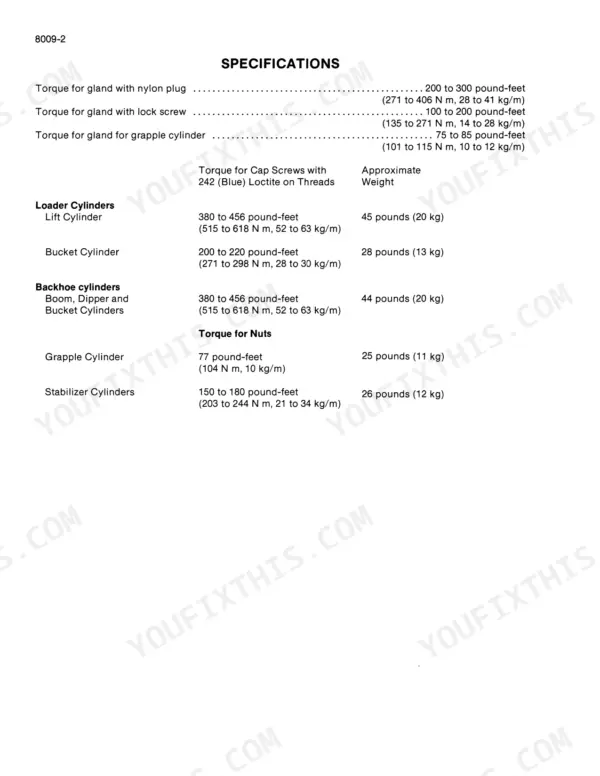
| Lift cylinder cap screws (242 Loctite) | 380 to 456 pound-feet (515 to 618 N m) | p. 964 |
Case 1835B Common Problems This Manual Covers
Hydrostatic charge pressure reads below 150 psi
Hydrostatic Test No. 1 on page 650 says the reading must not be less than 150 psi (1034 kPa) with the oil at operating temperature. If it is low, check the parts of the charge pressure relief valve. If those parts are good, check the charging pump output with Test No. 2.
Manual Section: Hydrostatic troubleshooting and diagrams p. 650Dual gear pump makes too much noise
The hydraulic troubleshooting chart on page 847 lists four causes. Loose pump cap screws get tightened to the correct torque value. Air entering the suction line gets repaired. Low reservoir oil gets topped up. A reservoir breather element that will not let air in gets replaced.
Manual Section: Hydraulic specifications, diagrams and tests p. 847Discharged batteries
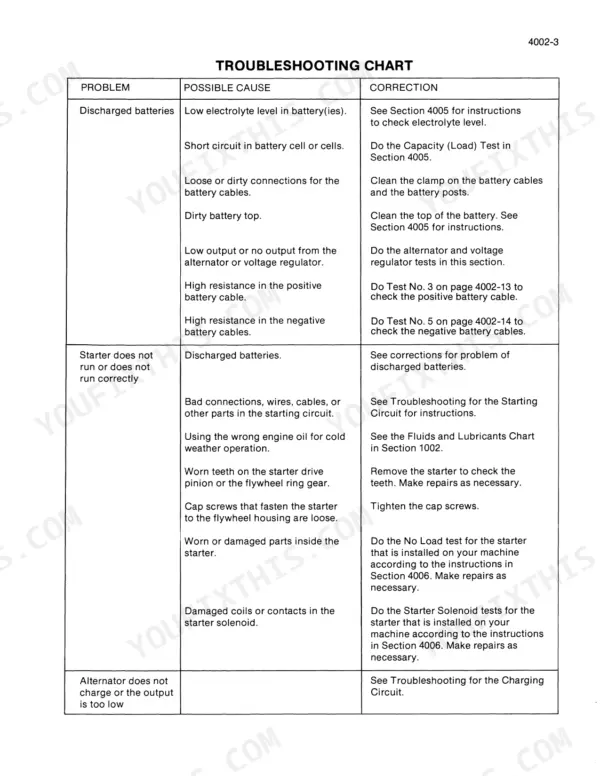
The electrical troubleshooting chart on page 539 lists low electrolyte level, loose or dirty cable connections, a dirty battery top, and low or no alternator or voltage regulator output. For high cable resistance, run Test No. 3 and Test No. 5. For shorted cells, do the Capacity (Load) Test in Section 4005.
Manual Section: Electrical troubleshooting and wiring diagrams p. 539Drive chain deflection more than 3/4 to one inch
Drive chains, pages 768-769: measure deflection at four points, turning the sprocket 90 degrees each time. Move the axle housing in its slots and tighten the self-locking nuts to 90 to 100 pound-feet (122 to 135 N m). If the housing cannot move far enough, replace the chain. Never remove a link. Each compartment holds 4 U.S. quarts (3.8 litres) of engine oil, drained and flushed with clean diesel fuel after 500 hours or yearly.
Manual Section: Hydrostatic controls and drive p. 768Frequently Asked Questions
What should the main relief valve read on the loader circuit?
The hydraulic specifications on page 838 give the loader main relief at 2275 to 2375 psi at full throttle (15 869 to 16 375 kPa). Backhoe is 2125 to 2225 psi at full throttle (14 651 to 15 340 kPa). The check sheet on page 863 runs Test No. 2 for loader circuits at 2275 to 2375 psi, engine speed 2000 rpm. The loader control valve section on page 896 prints 2200 to 2300 psi at full throttle, checked with oil at 120 F (49 C). Note which page you are setting to. p. 838
My machine moves slightly with the control levers in neutral. How do I set neutral?
Page 765 covers it. Raise the wheels off the floor and block the machine. Loosen the lock nut at the ball joint on the neutral control rod. Run the engine at low idle. Turn the neutral control rod with a screwdriver until the wheels stop turning. Hold the rod and tighten the lock nut. p. 765
How tight should the drive chains be, and can I shorten one by pulling a link?
Measure chain deflection at four points, turning the sprocket 90 degrees each time. It must not be more than 3/4 to one inch (19 to 25 mm) at any point. Tighten the axle housing self-locking nuts to 90 to 100 pound-feet (122 to 135 N m). A chain must be replaced when the axle housing cannot be moved in the slots to tighten it. The book says DO NOT remove a link to shorten the chain (pages 768-769). p. 768
What is the wheel nut torque spec on a Case 1835B Uni-Loader after removing a wheel?
Tighten wheel nuts to 80 to 90 pound-feet (108 to 122 N m, 11 to 12 kg/m) (page 13). After the wheels have been removed and installed, retighten after every 2 hours of operation until there is no change (page 14). p. 13
The starter does not run. What does the book point to?
The electrical troubleshooting chart on page 539 lists discharged batteries and bad connections in the starting circuit. For discharged batteries it lists low electrolyte level and loose or dirty cable connections. It also lists a dirty battery top and low or no output from the alternator or voltage regulator. High resistance in the battery cables sends you to Test No. 3 and Test No. 5. A shorted cell calls for the Capacity (Load) Test in Section 4005. p. 539










Reviews
There are no reviews yet.