
Part of the Case Repair Manuals.
This is the full factory service manual for the Case CX210D crawler excavator, the Tier 4 Final machine built around the Isuzu AR-4HK1X engine with SCR and EGR exhaust treatment. It covers everything from crankshaft and cylinder head work to the twin variable displacement pumps, main control valve, pilot circuit, swing and travel systems, and the boom, dipper, and bucket circuits. You also get the complete electrical section with harness schematic sheets, engine and hydraulic control systems, and a full fault code troubleshooting index built around a diagnostic scan tool. Undercarriage, tracks, track tension units, cab HVAC, glazing, and hood panels round it out. If you keep a 21700 kg CX210D earning its keep, this is the book the dealer techs use.
What's Inside This Case CX210D Manual
| System | Pages | Key Topics |
|---|---|---|
| Front Matter | 1-72 | Table of Contents, Introduction and Safety Information |
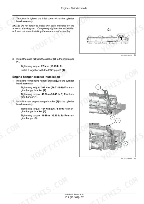
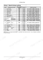
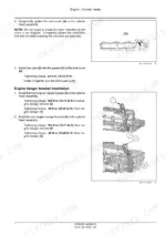
| Engine | 73-778 | Engine and Crankcase - General Specifications, Pan and Covers, Valve Drive and Gears, Cylinder Heads, Connecting Rods and Pistons, Crankshaft and Flywheel, Fuel Tanks, Fuel Filters, Fuel Injection System, Air Cleaners and Lines, Intake and Exhaust Manifolds and Muffler, Selective Catalytic Reduction (SCR) Exhaust Treatment, Exhaust Gas Recirculation (EGR) Exhaust Treatment, Engine Cooling System, Fan and Drive, Aftercooler, Engine Lubrication System |
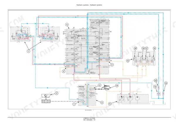
| Hydraulic Systems - Hydraulic Systems Overview | 779-991 | Swing Brake Circuit, Bucket Open Circuit Hydraulic Schema, Multi-Purpose Breaker Circuit, Main Relief Pressure Adjustment Procedure |
| Hydraulic Systems - Reservoir, Cooler, and Filters to Pump Control Valves | 992-1071 | Reservoir, Cooler, And Filters, Variable Displacement Pump, Pump Control Valves |
| Hydraulic Systems - Main Control Valve | 1072-1155 | Low-Pressure Relief Valve, Swing Spool Switchover, Stacked Add-On Control Valve Section, Main Pressure Control Valve Assembly |
| Hydraulic Systems - Pilot System and Pilot Solenoid Valve Block | 1156-1243 | 6-Stack Proportional Solenoid Valve Block, Pilot Accumulator, Hydraulic Hand Control Lever Assembly, Cushion Valve |
| Hydraulic Systems - Hydraulic Foot Control and Hydraulic Swing System | 1244-1349 | Travel Remote Control Pedal Valve, Swing Reduction Gear and Motor, Swing Relief Valve KRD22EK10, Pedal Control Troubleshooting Chart |
| Hydraulic Systems - Hydraulic Travel System | 1350-1461 | Counterbalance Valve Function, Automatic 2-Speed Travel Control, Travel Motor Disassembly and Relief Valve, Hydraulic Swivel (Central Joint) |
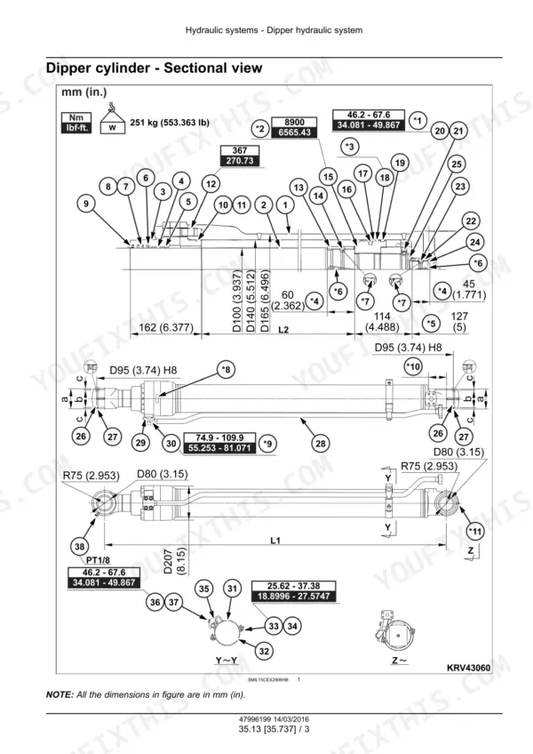
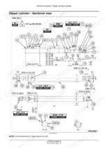
| Hydraulic Systems - Boom Cylinder Hydraulic System to Hammer and Rotating Bucket Hydraulic System | 1462-1558 | Boom Cylinder Hydraulic System, Dipper Hydraulic System, Excavator and Backhoe Bucket Hydraulic System, Hammer and Rotating Bucket Hydraulic System |
| Frames and Ballasting and Tracks and Track Suspension | 1559-1672 | Track Frame and Driving Wheels, Tracks, Track Tension Units, Track Rollers |
| Cab Climate Control | 1673-1718 | Heating, Air Conditioning |
| Electrical Systems - Electrical System Overview and Connectors | 1719-1879 | Starter Switch and Fuel Level Sensor, Air Conditioner Compressor Clutch, SCR Dosing Module and NOx Sensor, Camera Harness Routing |
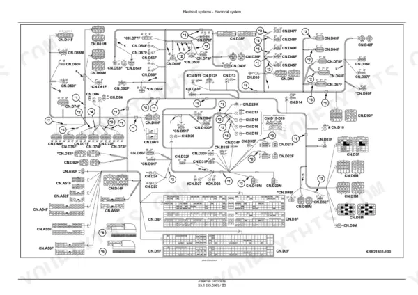
| Electrical Systems - Harnesses and Connectors (Schematic Sheets) | 1880-2311 | Connector Pinout Tables by Component (Room Lamp, Battery Cut Switch, Washer, Relay), Camshaft Position Sensor Connector, Boost Pressure Relief Solenoid Connector, Wire Colour and Pin Reference for Every Named Connector |
| Electrical Systems - Cab Engine Controls and Engine Control System | 2312-2393 | One-Touch Idle and Gate Lever Switch Logic, Engine Emergency Stop Function, CKP CMP and Oil Pressure Sensors, ECU Fault Code Index |
| Electrical Systems - Engine Starting System to Cold Start Aid | 2394-2489 | Engine Starting System, Alternator, Battery, Cold Start Aid |
| Electrical Systems - Fuel Injection Electrical System | 2490-2591 | Suction Control Valve and Fuel Shutoff Solenoid, Intake Air Pressure and Temperature Sensor, SCR Dosing Control Unit and NOx Sensor, DEF AdBlue Supply Module Removal |
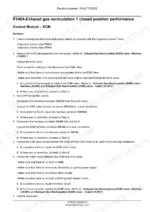
| Electrical Systems - Exhaust Gas Recirculation (EGR) Electrical System to Electronic Modules and Fault Code Index | 2592-2637 | Exhaust Gas Recirculation (EGR) Electrical System, Engine Cooling Electrical System, Engine Oil System (Electrical), Electronic Modules and Fault Code Index |
| Electrical Systems - Cab Controls | 2638-2821 | Monitor Display Judgment Condition Tables, SCR Manual and Auto Cleaning Procedure, Instrument Cluster Fuel Gauge and DTC Indicator, Screen Brightness Adjustment |
| Electrical Systems - Hydraulic System Control to HVAC Control System | 2822-2885 | Hydraulic System Control, Cab HVAC Controls, HVAC Control System |
| Electrical Systems - Cab Controls (Lift Arm, Boom, Dipper, Bucket) to Anti-Theft System | 2886-2963 | Cab Controls (Lift Arm, Boom, Dipper, Bucket), Swing Control System, Travel Control System, Camera, Wiper and Washer System, External Lighting, Cab Lighting, Warning Indicators, Alarms, And Instruments, Anti-Theft System |
| Electrical Systems - Fault Codes (DTC Troubleshooting) | 2964-3346 | Boom and Quick Coupler Sensor Fault Codes, Alternator and Crankshaft Position Correlation Codes, Urea Fluid Pressure and Temperature Sensor Codes, SCR System Error Codes |
| Booms, Dippers, and Buckets to Special Tool Index | 3347-3471 | Boom, Dipper Arm, Bucket, Cab and Platform, Cab Glazing, Mechanically-Adjusted Operator Seat, Engine Hood and Panels |
Quick Reference Specifications
| Specification | Value | Page |
|---|---|---|
| Engine Model | ISUZU AR-4HK1X | p. 27 |
| Rated flywheel horse power | 119.3 kW (162.2 Hp) at 1800 RPM | p. 27 |
| Operating mass | 21700 kg (47840 lb) | p. 30 |
| Fuel tank capacity | 410 L (108 US gal) | p. 48 |
| Hydraulic oil tank capacity | 147 L (38.8 US gal) | p. 48 |
| Maximum swing speed | 11.5 RPM | p. 27 |
| Travel speeds (High) | 5.6 km/h (3.5 mph) | p. 29 |
Case CX210D Common Problems This Manual Covers
Machine travels slow or weak on one side, or tracks pull to one side under load
The Hydraulic travel system section has you verify pressurized oil is actually reaching the travel motor inlet first, then work through the causes and countermeasures for each component in the circuit, so you isolate a valve or motor fault before pulling a final drive.
Manual Section: Hydraulic systems - Hydraulic travel system p. 1437Engine cranks but will not start, or starts hard when cold
The starting diagnosis begins with a fuel system inspection, then checks the coolant temperature sensor and fuel pressure sensor in order. Combined with the Engine starting system and Cold start aid sections, you can separate fuel delivery faults from sensor and starting circuit faults.
Manual Section: Electrical systems - Engine starting system to Cold start aid p. 2430Rough running or low idle speed, suspected bad injector on the common rail engine
The Fuel injection electrical system section includes an injector cut out test: when idle speed is low, you stop one injector at a time to check its condition, which pinpoints the weak cylinder without pulling injectors blind or swapping parts on a hunch.
Manual Section: Electrical systems - Fuel injection electrical system p. 2749Warning lamp on with an active fault code and no obvious symptom
The fault code section has you read the diagnostic trouble code information with the scan tool, then follow the test sequence for that specific code. The Electronic modules and fault code index cross references each code to its module, circuit, and schematic sheet.
Manual Section: Electrical systems - Fault codes (DTC troubleshooting) p. 3074Frequently Asked Questions
Does this manual cover fault codes and scan tool diagnostics, or is it just mechanical repair?
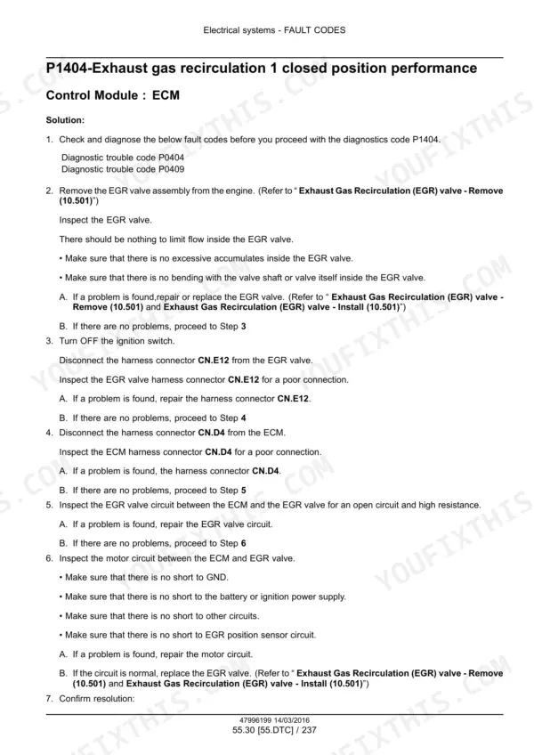
It covers both. There is a dedicated Fault codes (DTC troubleshooting) section plus an Electronic modules and fault code index. The workflow is the real dealer procedure: pull the diagnostic trouble code with the scan tool, then follow the step by step tests for that code through the sensors, harness, and module. The harness schematic sheets are included so you can trace circuits pin by pin. p. 3074
My CX210D cranks but will not start. Does the manual walk through that?
Yes, and it is a real procedure, not a flowchart poster. The no start diagnosis starts with the fuel system, then works through specific checks including the coolant temperature sensor and the fuel pressure sensor. Since this is a common rail engine, the manual ties those tests into the fuel injection electrical system section so you can tell a fuel supply problem from a sensor or control problem before you spend money on parts. p. 2430
Are the hydraulic test pressures in here so I can actually check the pumps and relief valves?
They are. Working circuit pressure for boom, arm, and bucket is 34.3 MPa (4975 psi), rising to 37.3 MPa (5410 psi) with auto power up. Swing runs 29.4 MPa (4265 psi), travel 34.3 MPa (4975 psi), and the pilot circuit 3.9 MPa (566 psi). Pump flow specs are listed too, so you can verify the two main pumps against their rated output at 1800 RPM instead of guessing. p. 27
Does it cover the DEF/SCR emissions system? That is where these Tier 4 machines cause grief.
Yes. There are dedicated sections for the Selective Catalytic Reduction exhaust treatment and the Exhaust Gas Recirculation system, on both the mechanical side and the electrical side, including the EGR electrical system and its fault codes. Capacities are listed as well, including the 120 L (31.7 US gal) DEF tank, so service fills and system checks are all documented. p. 48
Which machines does this manual fit, and what engine specs does it list?
It is for the Case CX210D crawler excavator with the Isuzu AR-4HK1X engine, rated 119.3 kW (162.2 Hp) at 1800 RPM with 620 N·m (457 lb ft) of torque at 1600 RPM, with some configurations listed at 124 kW (169 Hp). Fuel tank is 410 L, hydraulic tank 147 L, total hydraulic system 250 L. If your serial plate says CX210D, this is the right book. p. 27








Reviews
There are no reviews yet.