Part of the Case IH Repair Manuals.
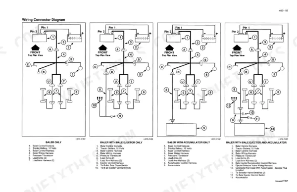
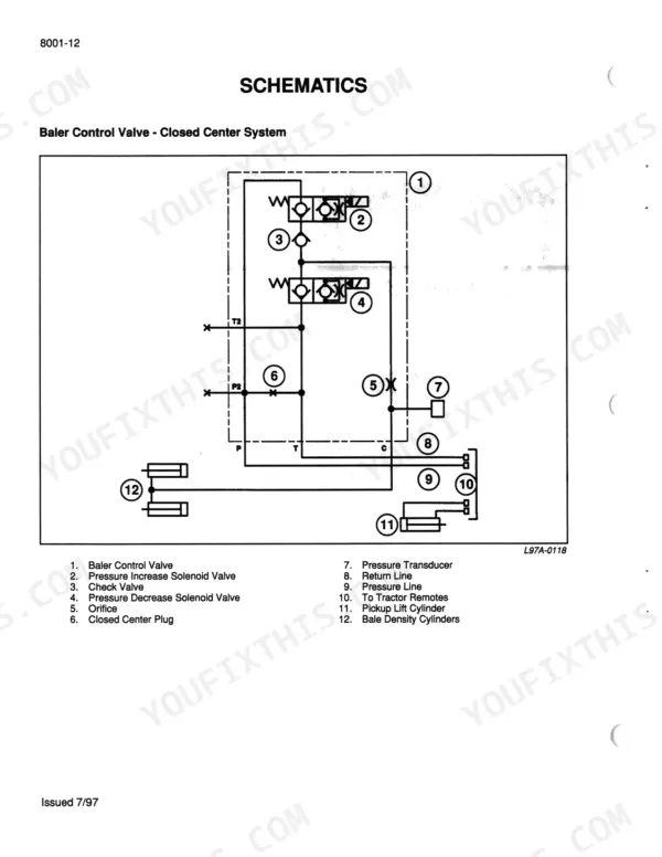
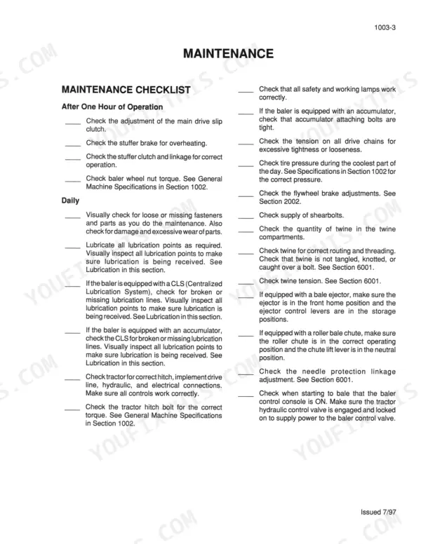
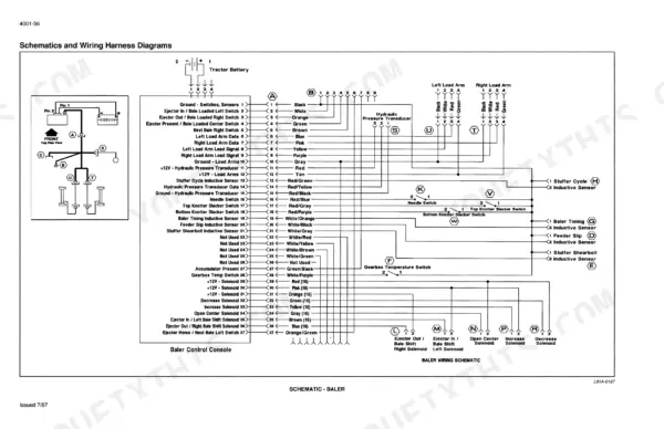
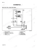
Knotter service, flywheel brake work and main drive clutch setup on the Case IH 8575 baler and accumulator are laid out in this 719-page Case IH 8575 service manual PDF, factory publication Rac 7-81760. Electrical schematics come paired with circuit troubleshooting, and the hydraulic schematics explain system operation before moving into control valves and cylinders. Pickup adjustments and gauge wheels, packer, stuffer and charge chamber, plunger, bale tension, axle and centralized lubrication are covered too. The figures are factory numbers. Hold the packer finger bearing gap to 0.003 to 0.010 in (0.08 to 0.25 mm), then tighten the main drive shaft yoke nut to 150 lb-ft (205 N·m). When you check the reel drive chain, look for 1/2 in (13 mm) of deflection under 40 lb (174 N) of force. Bookmarks and a searchable text layer jump straight to the gearbox or knotter pages, so you can confirm the exact assembly before ordering a replacement.
What's Inside This Manual
| System | Pages | Key Topics |
|---|---|---|
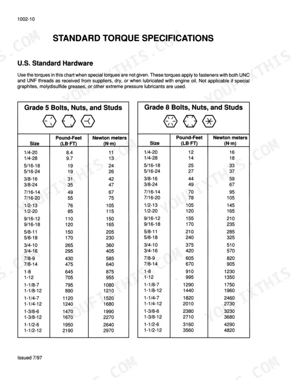
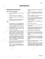
| General | 3-58 | Introduction, Safety Rules, General Machine Specifications, And Standard Torque Specifications, Maintenance and Lubrication, Decals |
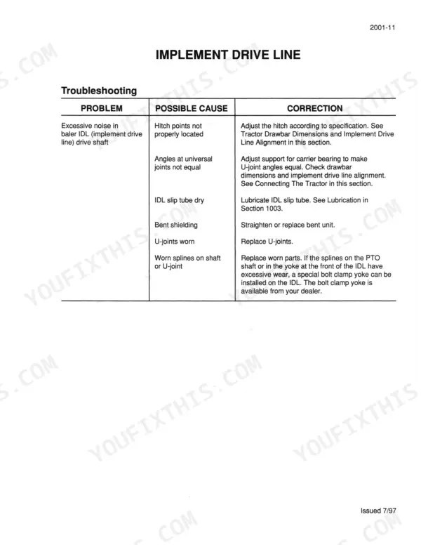
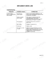
| Drive System | 59-174 | Connecting the Tractor, Implement Drive Line, Main Drive Shaft, And Main Drive Clutch, Flywheel, Flywheel Brake, And Gearbox, Auxiliary Drives |
| Pickup | 175-210 | Pickup Operation, Adjustments, Gauge Wheels, And Troubleshooting |
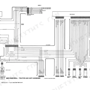
| Electrical System | 211-340 | Electrical Schematics and Troubleshooting |
| Feeder and Plunger | 341-416 | Packer, Stuffer and Charge Chamber, Plunger |
| Knotter System | 417-528 | Knotter |
| Mainframe, Bale Tension, and Wheels | 529-554 | Mainframe and Bale Tension, Axle, Wheels, And Tires |
| Hydraulic System | 555-672 | Hydraulic System Operation, Schematics, Control Valves, Cylinders, And Troubleshooting |
| Optional Equipment | 673-719 | Centralized Lubrication System, Accumulator, Bale Chutes, Bale Ejector, And Selector Valve |
Every system also includes an index.
Quick Reference Specifications
| Specification | Value | Page |
|---|---|---|
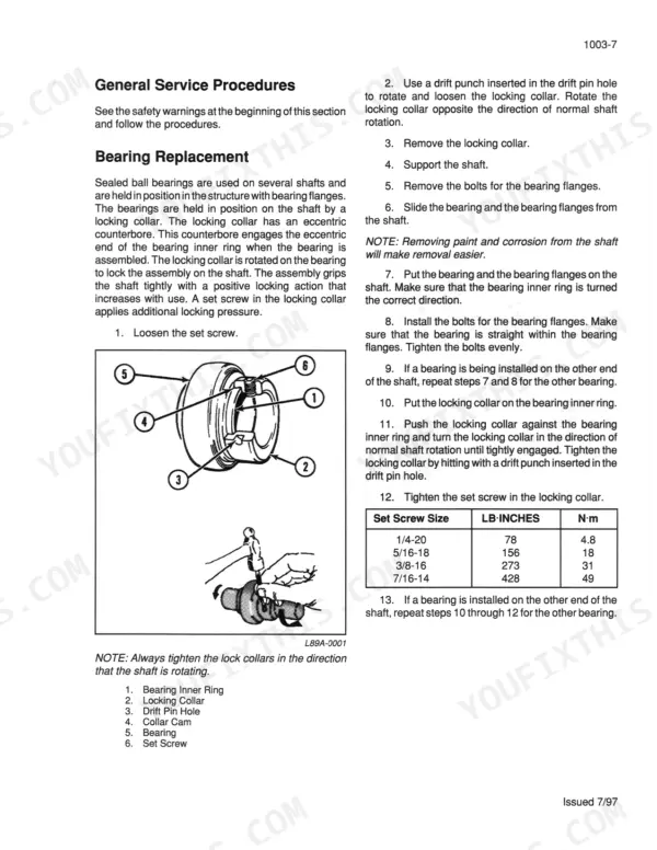
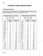
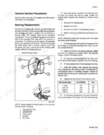
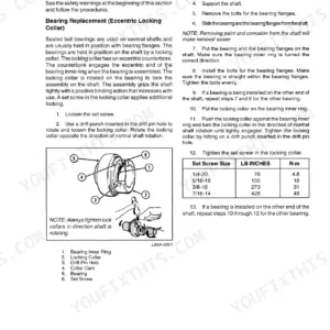
| Set screw torque for bearing locking collar | 1/4-20: 78 LB-INCHES (4.8 N·m), 5/16-18: 156 LB-INCHES (18 N·m), 3/8-16: 273 LB-INCHES (31 N·m), 7/16-14: 428 LB-INCHES (49 N·m) | p. 27 |
| Packer finger bearing gap | 0.003 to 0.010 IN (0.08 to 0.25 mm) | p. 351 |
| Main drive shaft yoke nut torque | 150 LB-FT (205 N·m) | p. 73 |
| Clamp yoke bolt torque | 76 LB-FT (105 N·m) | p. 73 |
| Reel drive chain deflection | 1/2 IN (13 mm) with 40 LB (174 N) of force | p. 182 |
| Right-hand auger drive chain deflection | 1/2 IN (13 mm) with 40 LB (174 N) of force | p. 182 |
| Tractor voltage minimum for baler control console | 12 volts | p. 320 |
| Tractor voltage maximum for baler control console | 18 volts DC | p. 320 |
| Pressure decrease solenoid valve nut torque | 5 LB-FT or 60 LB-INCHES (7 N·m) | p. 612 |
| Minimum tractor hydraulic system pressure | 2200 psi | p. 608 |
| Main Drive PTO Speed | 1000 rpm | p. 14 |
| Baler Tire Pressure | 38 psi | p. 14 |