
Part of the Case IH Repair Manuals.
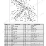
Hydrostatic drive, rear PTO, three-point hitch hydraulics, and the full electrical system: this Case IH Farmall 20B, Farmall 25B service manual PDF walks every one of them end to end across 758 pages, issued under OEM number 47576301. Factory wiring diagrams trace each harness and connector, from the cold start aid through the parking brake circuit and PTO controls, while hydraulic schematics map oil flow through the fixed displacement pump, hitch control valve, and remotes. Exploded views and troubleshooting charts back up teardown procedures for the front axle, hydrostatic transmission, brakes, and steering. Rear wheel discs go back on the axle at 176 to 196 N·m (130 to 145 lb ft); the hydrostatic transmission retaining bolts take 29.4 to 34.3 N·m (22 to 25 lb ft). A hydro that creeps in neutral will not wait for dry weather. Bookmarked and text searchable, your copy rides along wherever you park the tractor, shop bench or headland.
What's Inside This Case IH Farmall 20B, Farmall 25B Manual
| System | Pages | Key Topics |
|---|---|---|
| International Symbols | 9 | Thermostart, Alternator Charge, Fuel Level, Engine Speed, Engine Oil Pressure, Engine Coolant Temperature |
| Safety Rules | 10-14 | Personal Safety, Machine Safety, Accident Prevention, Fluid Power Systems, Safety Frame (ROPS), Diesel Fuel |
| Basic Instructions - Important Notice Regarding Equipment Servicing | 15 | Dealership Personnel, Special Tools, Manufacturer Responsibility, Continuous Improvement |
| Basic Instructions - Shop and Assembly | 16-17 | Shimming, Rotating Shaft Seals, O-Ring Seals, Sealing Compounds, Spare Parts |
| Basic Instructions Hardware | 18 | Metric Hardware, Plating, Nut Tightening, Locknuts, Jam Nuts, Thread Lubrication |
| Torque Specification Tables | 19-23 | Inch Non-Flanged Hardware, Metric Non-Flanged Hardware, Sae Hardware Identification, Metric Hardware Identification, Definitions |
| General Specification | 24-27 | Engine, Cooling System, Electrical System, Fuel System, Brakes, Steering |
| General Specification - Biodiesel Fuels | 28 | Biodiesel Fuel Usage Conditions, Engine Performance, Cold Weather Conditions, Fuel Storage |
| Dimension | 29-31 | Length, Wheel Base, Top of ROPS, Width, Minimum Ground Clearance, Wheel Tread Settings |
| Consumables | 32 | Engine Oil, Transmission/Hydraulic Oil, Front Axle/Gear Oil, Grease, Coolant |
| Product Identification | 33-34 | Product Identification Plate, Frame Location, Serial Number |
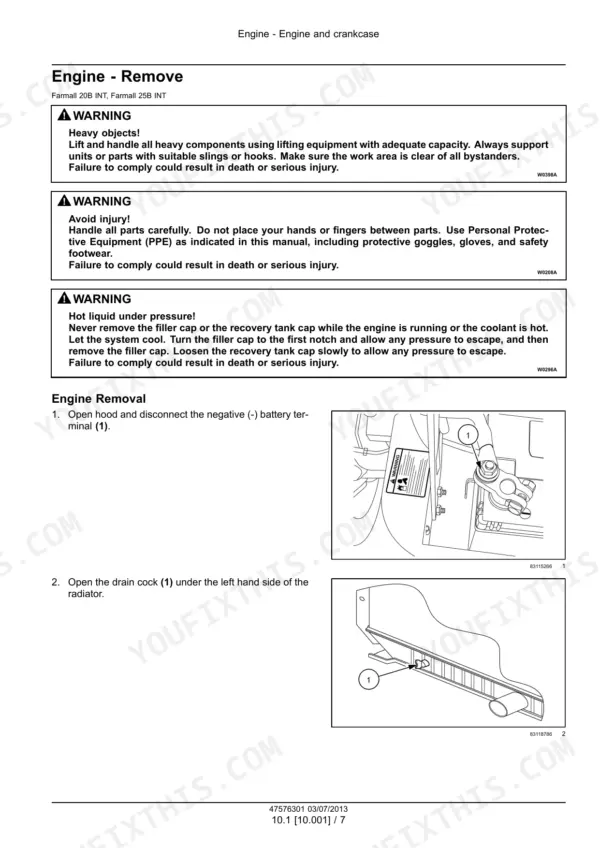
| Engine | 35-62 | Engine and Crankcase, Engine Lubrication System, Engine Cooling System |
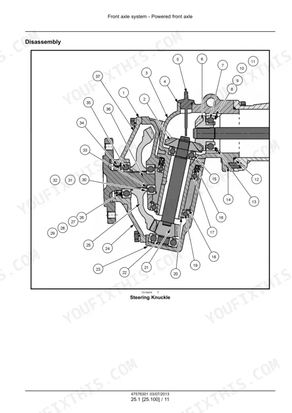
| Front Axle System | 63-122 | Powered Front Axle, Front Bevel Gear Set and Differential, Final Drive Hub, Steering Knuckles, And Shafts |
| Rear Axle System | 123-150 | Rear Bevel Gear Set and Differential, Final Drive Hub, Steering Knuckles, And Shafts |
| Hydrostatic Drive | 151-256 | Transmission and Steering Hydrostatic Control, Hydrostatic Transmission, Reservoir, Cooler, And Lines, Pump and Motor Components |
| Power Take-Off (PTO) | 257-326 | Rear Mechanical Control, Rear Electro-Hydraulic Control, One-Speed Rear Power Take-Off, Central Power Take-Off |
| Brakes and Controls | 327-352 | Parking Brake or Parking Lock, Mechanical Service Brakes |
| Hydraulic Systems | 353-448 | Hydraulic Systems Overview, Fixed Displacement Pump, Three-Point Hitch Control Valve, Three-Point Hitch Cylinder, Remote Control Valves, Reservoir, Cooler, And Filters |
| Hitches, Drawbars, and Implement Couplings | 449-458 | Rear Three-Point Hitch |
| Steering | 459-534 | Tie Rods, Hydraulic Control Components, Cylinders |
| Wheels | 535-548 | Front Wheels, Rear Wheels |
| Electrical Systems | 549-748 | Electrical System, Fuel Injection System, Fuel Tank System, Engine Cooling System, Engine Oil System, Parking Brake Electrical System, Rear Power Take-Off Control System |
| Platform, Cab, Bodywork, and Decals | 749-758 | Mechanically-Adjusted Operator Seat |
Quick Reference Specifications
| Specification | Value | Page |
|---|---|---|
| All Models | ||
| Front Wheel Disc-to-Hub Torque | 93 - 108 N·m (69 - 80 lb ft) | p. 23 |
| Rear Wheel Disc-to-Axle Torque | 176 - 196 N·m (130 - 145 lb ft) | p. 23 |
| Disc Diameter | 223 mm (9 in) x 174 mm (7 in) | p. 337 |
| Disc Outer Diameter | 114 mm (4.5 in) | p. 337 |
| Fuel Tank Capacity | 25 l (6.6 US gal) | p. 24 |
| Engine Crankcase Oil Capacity (with filter) | 4 l (1.10 US gal) | p. 24 |
| Radiator Cap Pressure | 90 kPa (13 psi) | p. 24 |
| Hydraulic Lift System Pump Capacity | 27 l (7 US gal) | p. 26 |
| Hydraulic System Relief Valve Setting | 14997 kPa (2175.1 psi) | p. 26 |
| ROPS to Rear Axle Attaching Bolt Torque | 85 N·m (63 lb ft) | p. 27 |
| Farmall 20B | ||
| Engine Gross Horsepower (Farmall 20B) | 17 kW (23 Hp) | p. 24 |
| Farmall 25B | ||
| Engine Gross Horsepower (Farmall 25B) | 20 kW (27 Hp) | p. 24 |
Case IH Farmall 20B, Farmall 25B Common Problems This Manual Covers
Case IH Farmall 25B hydrostatic transmission jerky in forward, creeps and will not stop at neutral
Check the transmission oil level and change the HST filter before condemning the pump. Inspect the neutral return linkage for wear at the pedal pivot points. Trace the charge circuit against the hydraulic schematic. If you pull the filter housing, torque the HST retaining bolts to 29.4 - 34.3 N·m (22 - 25 lb ft) on reassembly.
Manual Section: Hydrostatic Drive p. 151Brake pedal goes soft and tractor pulls to one side when both pedals are locked together
Measure brake pedal free travel and set it to 70 - 80 mm (2.76 - 3.15 in) per page 347 before splitting anything. If adjustment will not even up the pedals, pull the discs and check them against the 0.4 mm minimum wear limit on page 337, torquing the cover plate bolts to 49 - 54 N·m (36 - 40 lb ft) on reassembly.
Manual Section: Brakes and Controls p. 327Three point hitch will not lift a loaded planter, drops to the ground with engine running
Check the transmission oil level first; a low reservoir starves the lift pump. Verify relief valve pressure against the 14997 kPa (2175.1 psi) setting listed on page 26. Inspect the three-point hitch control valve and cylinder for internal leakage using the procedures starting on page 353. If pressure checks good, look for a scored lift cylinder before blaming the pump.
Manual Section: Hitches, Drawbars, and Implement Couplings p. 449Low oil pressure warning light flickers at hot idle and stays on after restart
Check the oil level on level ground before anything else. Drain and refill the crankcase; it holds 4 l (1.10 US gal) with a new filter. Work through the lubrication troubleshooting steps on page 55 to separate a bad sender from a worn pump. If the light still misbehaves, test the circuit against the wiring diagram.
Manual Section: Engine Lubrication System Troubleshooting p. 55Coolant pushes out the overflow and temperature gauge climbs during heavy loader or mower work
Clean the radiator core and screen with low pressure air from the fan side. Pressure test the cap and replace it if it will not hold 90 kPa (13 psi), the setting listed on page 24. Check coolant level cold, inspect the lower hose for collapse under load, and verify fan belt tension before you lose a mowing day.
Manual Section: Engine Cooling System TroubleshootingFrequently Asked Questions
What are the torque specifications for the Farmall 20B and 25B front wheel bolts?
The torque specification for the front wheel disc-to-hub bolts on the Farmall 20B and 25B is 93 - 108 N·m (69 - 80 lb ft). p. 27
What is the engine oil capacity for the Farmall 20B and 25B?
The engine crankcase oil capacity for both the Farmall 20B and 25B, including the filter, is 4 liters (1.10 US gallons). p. 24
What is the correct valve clearance for the intake and exhaust valves on the Farmall 20B and 25B engines?
For both the Farmall 20B and 25B engines, the intake valve clearance is 0.020 - 0.050 mm (0.0008 - 0.0020 in) and the exhaust valve clearance is 0.050 - 0.085 mm (0.0020 - 0.0033 in). p. 24
What is the torque specification for the cylinder head bolts on the Farmall 20B and 25B engines?
The cylinder head bolts on the Farmall 20B and 25B engines should be tightened to a torque of 83 - 93 N·m (61 - 69 lb ft). p. 42
What is the required resistance for the engine coolant temperature sending unit at 80 °C?
At a temperature of 80 °C (176 °F), the engine coolant temperature sending unit should have a resistance of 73 Ω. p. 115
Will this Case IH Farmall 20B Service Manual download right away?
You download the Service Manual yourself: 758 pages, searchable PDF, available immediately. Keep a copy on every device you use.
Can I print a copy of this Case IH Farmall 20B Service Manual for the shop?
Yes. Many buyers print one chapter at a time for their own shop and keep the rest on a tablet.





Reviews
There are no reviews yet.