

Part of the Case Repair Manuals.
An hour from now you could be tracing a dead circuit instead of staring at it: this 394 page PDF is one volume of the Case Magnum 215-335 factory service set (84170101), the electrical schematics and lighting book A.30.A to A.40.A, OEM 84176636, covering five Magnum series tractors from the 215 through the 335 from P.I.N. Z7RZ05000 and after. Check your tractor's P.I.N. plate before you buy: the schematic frames are printed twice, once for Z7Rx05001 through Z8Rx06000 and again for Z8Rx06001 and later, so both serial breaks are covered in this one file. Connector diagrams take up most of the book, mapping each plug pin by pin, with fuse and relay box identification split by the same serial number break. Electrical schematic frames trace every circuit from fuse to splice, and diagnostic routines walk you through relay testing, alternator testing, and lighting system faults. Check charging output against the 14.2 V regulation spec before condemning a battery, then torque the regulator screws to 0.7 to 1.0 Nm on reassembly. Guessing buys the wrong part and a second teardown.
What's Inside This Case Magnum 215–335 Manual
| System | Pages | Key Topics |
|---|---|---|
| Connectors - Component Diagrams | 5-14 | Connector Identification, Component Diagrams, Connector Frame Locations, Reference Designators |
| Wiring Harness - Schematic Frames 01-52, PIN Z7Rx05001-Z8Rx06000 | 15-113 | Electrical Schematic Frames, Circuit Descriptions, Pneumatic Brake, Back Up Alarm Harness, Splices |
| Wiring Harness - Schematic Frames 53-90, PIN Z7Rx05001-Z8Rx06000 | 114-213 | Electrical Schematic Frames, Seat Harness, Terra Lock, Load Pressure Sensor, Splice Tables |
| Wiring Harness - Schematic Frames, PIN Z8Rx06001 and After | 214-347 | Charging and Starting System, Suspended Axle, Outside Autoguidance, Strobe Lamp Circuits, Splice Tables |
| Alternator and Battery - Service | 348-354 | Alternator Replace, Regulator Replace, Battery Disconnect, Battery Connect |
| Fuse and Relay Box - Problem Solving | 355-361 | Power Distribution, Relay Testing, Cab Power Relays, Tractor ECU Relay, Armrest Controller Relay |
| Alternator - Problem Solving | 362-366 | Charging System Output, Regulation Voltage, Alternator Testing |
| Connectors - Component Diagrams (Continued) | 367-374 | Connector Identification, Component Diagrams, Serial Number Breaks |
| Lighting System | 375-394 | High Beam Circuits, Rear Work Light Switch Testing, Dome Light Testing, Problem Cause Correction Tables, Test Point Tables |
Quick Reference Specifications
| Specification | Value | Page |
|---|---|---|
| Charging system output at 1000 RPM, transmission in Park | 12.8 - 14.5 V | p. 363 |
| Alternator voltage regulation | 14.2 V | p. 362 |
| Cab power relay supply, terminal 240M to chassis ground, key off | 12 V | p. 356 |
| Alternator regulator screw torque (3 mm) | 0.7 - 1.0 Nm | p. 351 |
| Alternator regulator screw torque (5 mm) | 4.0 - 5.0 Nm | p. 351 |
| Alternator cover nut torque | 4.0 - 5.0 Nm | p. 352 |
Case Magnum 215–335 Common Problems This Manual Covers
Case Magnum 335 charge light on, batteries dead after sitting overnight, alternator not charging
Check charging output first: with the engine at high idle, voltage at the batteries should hold near 14.2 V. If it stays at battery voltage, work through the alternator problem solving chart on page 362, then test the excitation and RPM circuits before condemning the alternator. Clean and tighten the ground connections while you are in there.
Manual Section: Alternator - Problem solving p. 362Overcharging message on the monitor, batteries boiling and using water, voltage climbing past normal
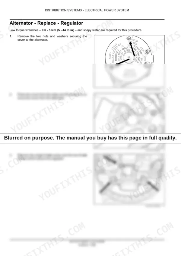
Test voltage at the batteries with the engine running; anything well above 14.2 V means the regulator has failed. Replace the regulator: torque the 3 mm screws to 0.7 to 1.0 Nm and the 5 mm screws to 4.0 to 5.0 Nm per page 351, then torque the cover nuts to 4.0 to 5.0 Nm from page 352.
Manual Section: Service p. 351No power in the cab, gauges and display dead, engine still cranks over fine
Check the fuse and relay box before anything else: the power distribution problem solving section starts on page 355, and the cab power relay test follows on page 356 — with the key switch off you should read 12 V between ring terminal connector 240M and chassis ground. Clean any corroded terminals in the box while you are in there. Once power is restored, run the engine and confirm the system charges at 14.2 V so the batteries recover fully.
Manual Section: Fuse and relay box - Power distribution p. 355High beams do not illuminate, low beams work, or neither beam comes on
The lighting problem solving table on page 378 points at the universal switch for both cases. Work the head light switch test for the universal switch in section A.40.A, then follow the lighting schematic frames to check the feed and ground at the lamp before you replace a headlight assembly.
Manual Section: Lighting system - Problem solving p. 378Frequently Asked Questions
What is the torque spec for the alternator regulator screws on a Case Magnum 215-335 tractor?
The 3 mm screw should be torqued to 0.7 - 1.0 Nm (6 - 9 lb in), and the two 5 mm screws should be torqued to 4.0 - 5.0 Nm (35 - 44 lb in). p. 351
What is the procedure for disconnecting the battery?
To disconnect the battery, first loosen the two left thumbscrews and remove the two right thumbscrews to remove the toolbox and battery cover. Then, disconnect the negative (-) battery cable first, followed by the positive (+) battery cable. p. 353
How do I test the cab power relays?
Testing involves checking for 12 V at specific terminals (240M, 239FF, 138AC, 138AD, 138BB) while the key switch is in the On or Off position, and verifying resistance to ground at terminal 279FF is less than 1 ohm. p. 356
What is the procedure for testing the alternator charging system output?
With the transmission in Park and the engine running at 1000 RPM, measure battery voltage, which should be between 12.8 - 14.5 V. Additionally, check for voltage drops of less than 0.4 V between the battery positive post and the starter terminal 81A, and between the alternator terminal 77F and starter terminal 81F. p. 363
How do I test the dome light circuit?
Testing involves checking for 12 V at connector 102M, verifying the ground circuit at the door switch (less than 1 ohm), and checking the switch continuity when moved to the On position. p. 390
Is this a download or a disc?
You get a 394-page searchable PDF that downloads instantly after checkout. Open it on your laptop, tablet, or phone, and bring it right to the shop floor.
Can I print just the pages I need?
Yes. Print a single page or a chapter for your own shop use, on letter or A4.










Reviews
There are no reviews yet.