


Part of the Hyundai Repair Manuals.
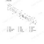
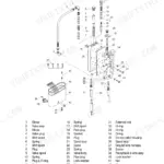
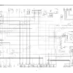
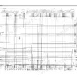
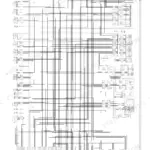
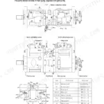
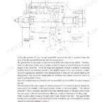
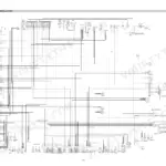
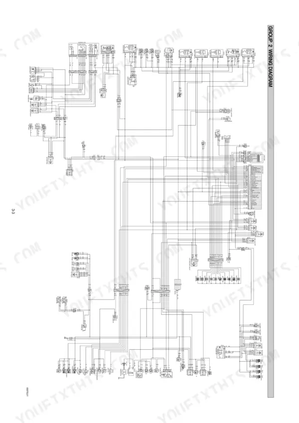
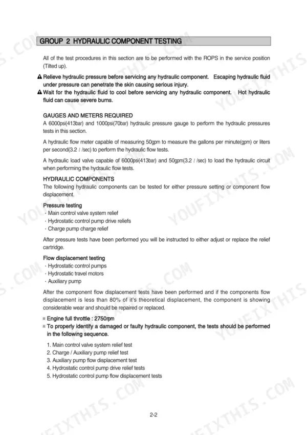
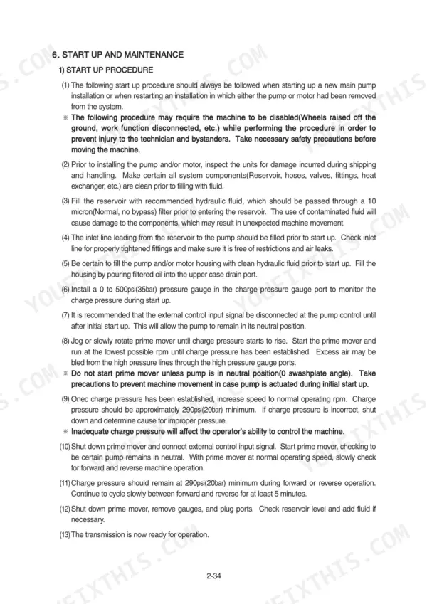
Chasing hydraulic pressures for your skid steer? This 138-page Hyundai HSL650-7 Service Manual PDF walks the whole loader, from safety and maintenance intervals through the hydrostatic drive to final troubleshooting. You get the complete hydraulic circuit diagram with component testing procedures, full electrical wiring diagrams with component locations, and troubleshooting logic charts for the transmission's closed circuit. Step-by-step teardowns take you through the main and auxiliary pumps, travel motors, main control valve, self-level valve, and boom and bucket cylinders, with reassembly torques included. Set the main relief at 175 kgf/cm2 (2490 psi), torque the pump mounting nuts to 19.6 kgf·m (142 lbf·ft), and change fluid and filter every 500 hours. No more bleeding a hydrostatic system on guesswork. Bookmarked with a real text layer: search a spec, jump to the section, pull it up on your phone in the shop.
What's Inside This Manual
| System | Pages | Key Topics |
|---|---|---|
| General | 1-21 | Safety Hints, Specifications, Maintenance |
| Hydraulic Circuit and Component Testing | 22-29 | Hydraulic Circuit Diagram, Component Testing Procedures, Main Control Valve Pressure, Auxiliary Pump Flow, Hydrostatic Control Pump Pressure |
| Self Level Valve | 30-35 | Self Level Valve Structure, Hydraulic Circuit, Self Leveling Operation, Bucket Cylinder Extension, Retracting Boom Cylinder |
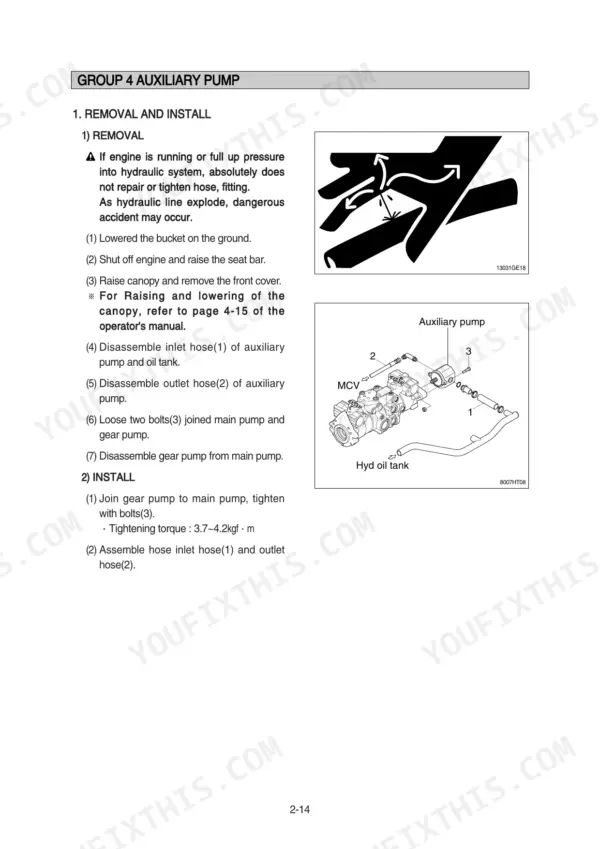
| Auxiliary Pump and Main Pump | 36-50 | Auxiliary Pump Removal and Installation, Pump Disassembly and Assembly, Main Pump Removal and Installation, Main Pump Structure |
| Transmission Hydraulic Support System | 51-61 | Transmission General Description, Basic Closed Circuit, Charge System, High Pressure Relief Valves, Troubleshooting Logic Diagrams |
| Inspections, Adjustments, and Maintenance | 62-70 | Manual Displacement Control, Relief Valve Inspection, Neutral Bracket Adjustment, Control Spool Disassembly |
| Travel Motor | 71-83 | Travel Motor Removal and Installation, Travel Motor Structure, Travel Motor Disassembly and Assembly, Reassembly Procedures |
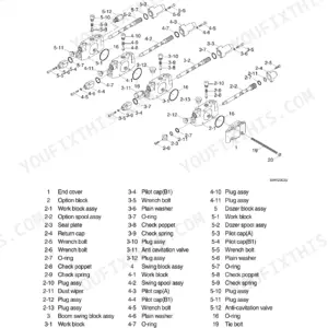
| Main Control Valve | 84-91 | Main Control Valve Removal and Installation, Valve Structure, Boom Spool Disassembly, Bucket Spool Disassembly, Load Check Valve |
| Boom and Bucket Cylinders | 92-96 | Cylinder Removal and Installation, Cylinder Structure, Cylinder Disassembly and Assembly, Tightening Torque Specifications |
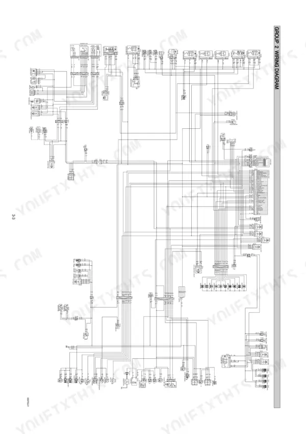
| Electrical System | 97-116 | Component Location, Wiring Diagram |
| Power Train | 117-122 | Power Train Component, Front and Rear Axle |
| Control | 123-129 | Hand Control, Parking Brake, Attachment Holder |
| Troubleshooting | 130-138 | Travel Hydraulics, Boom and Bucket Hydraulic, Power Train, Control, Electrical System |
Quick Reference Specifications
| Specification | Value | Page |
|---|---|---|
| Main pump capacity | 2 x 46 cc/rev | p. 13 |
| Main pump maximum operation pressure | 250 kgf/cm2 (3560 psi) | p. 13 |
| Nut(2) tightening torque | 19.6±2.9kgf·m (142±21.0lbf·ft) | p. 46 |
| Bolt(3) tightening torque | 6.9±1.4kgf·m (49.9±10.1lbf·ft) | p. 46 |
| Fluid and filter change interval | 500hrs | p. 57 |
| Tightening torque for mounting bolt(4) | 12.8 ± 3.0 kgf·m (92.6 ± 21.7 lbf·ft) | p. 72 |
| Tightening torque for cover(2) bolt(1) | 6.9 ± 1.4 kgf·m (49.9 ± 10.1 lbf·ft) | p. 72 |
| Tightening torque for cover(23) and bearing(21) screw(34) | 27 to 31.8 kgf·m (195 to 230 lbf·in) | p. 81 |
| Tightening torque for 4 hexagonal bolts(65) | 164.5 to 177 kgf·m (1190 to 1280 lbf·in) | p. 83 |
| Oil quantity | 10.5 L (2.8 U.S.gal) | p. 121 |
| Engine oil quantity | 7.6 L | p. 15 |
| Main relief valve pressure | 175 kgf/cm2 | p. 14 |