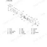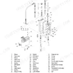


Part of the Hyundai Repair Manuals.
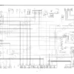
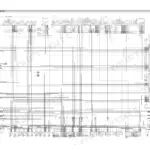
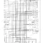
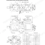
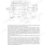
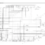
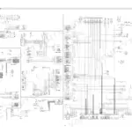
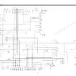
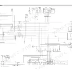
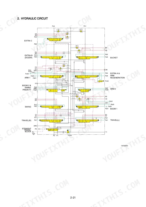
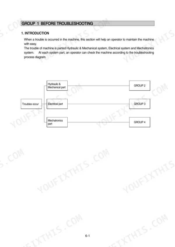
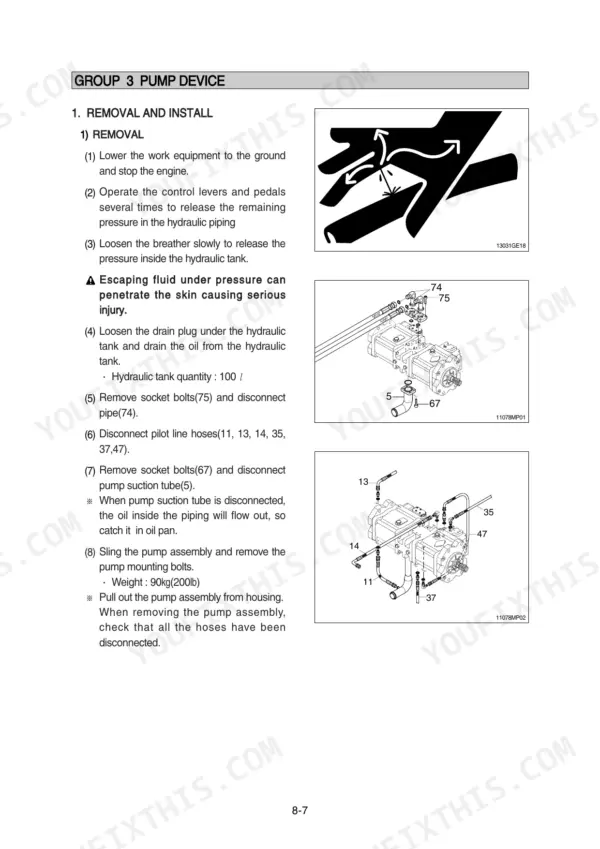
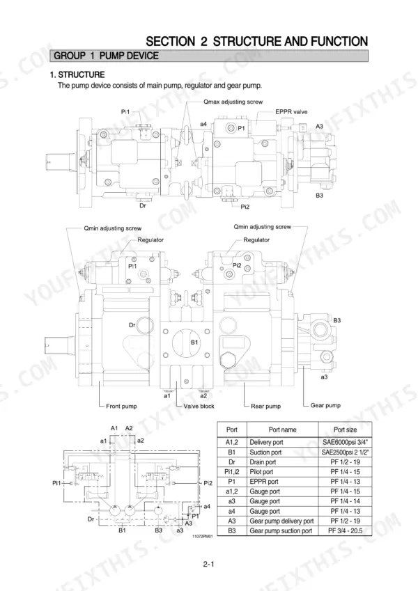
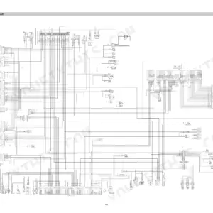
Looking for the Hyundai R110-7, R110D-7 service manual PDF? All 504 pages take this hydraulic excavator from factory teardown to final torque check: pump device, main control valve, swing and travel drives, RCV lever and pedal. You get hydraulic circuit schematics tracing the pilot and main circuits through single and combined operation, wiring diagrams with full connector tables, and a self-diagnostic section that decodes the CAPO system's error codes. Inside: step-by-step disassembly and assembly for the pump, swing device, travel motors, turning joint, and every cylinder on the boom, arm, and bucket. Set the main relief valve to 330 kgf/cm2 (4695 psi), 360 with power boost engaged, and fill the hydraulic tank to 100 liters. No more chasing pressure faults with a gauge and a hunch. Bookmarked and keyword-indexed, so you jump straight to the spec your machine needs.
What's Inside This Manual
| System | Pages | Key Topics |
|---|---|---|
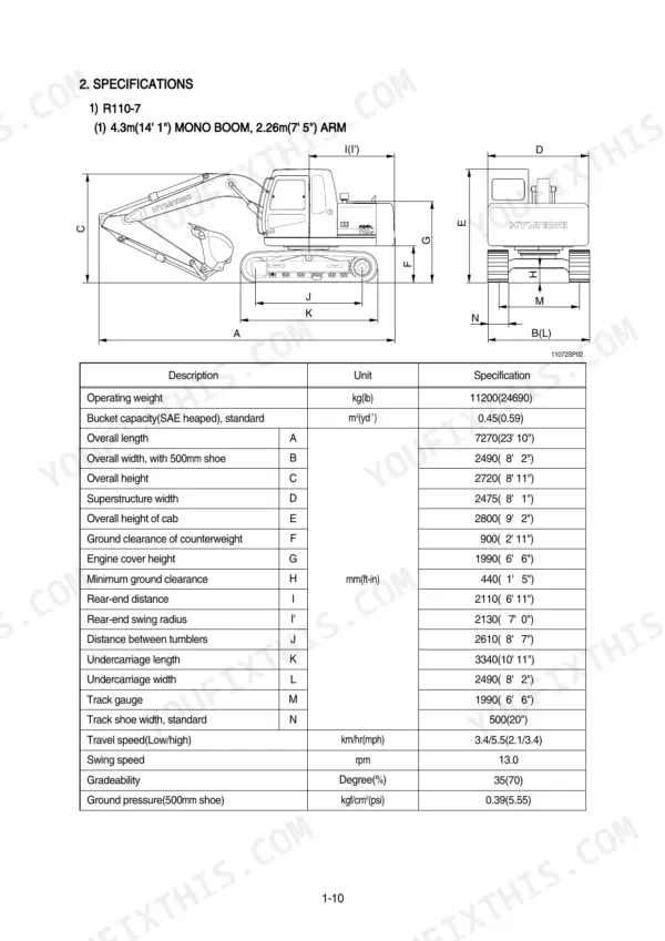
| General | 1-18 | Safety Procedures, Protective Clothing, Emergency Preparedness, Machine Specifications, Major Components |
| Structure and Function | 35-114 | Pump Device, Regulator, Gear Pump, Main Control Valve, Swing Device, Travel Device, Rcv Lever, Rcv Pedal |
| Hydraulic System | 115-158 | Hydraulic Circuit, Main Circuit, Pilot Circuit, Single Operation, Combined Operation, Swing Priority System |
| Electrical System | 159-206 | Component Location, Electrical Circuit, Connectors, Connector Destination, Connector Tables |
| Mechatronics System | 207-237 | Capo System Outline, Mode Selection, Power Boost, Travel Speed Control, Self-Diagnostic System, Error Codes |
| Maintenance Standard | 293-326 | Operational Performance Test, Major Components, Track and Work Equipment, Swing Bearing Play, Cylinder Cycle Time |
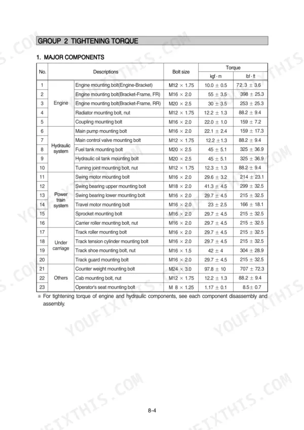
| Disassembly and Assembly | 327-481 | Precaution, Tightening Torque, Pump Device, Main Control Valve, Swing Device, Travel Device, Rcv Lever, Turning Joint |
| Component Mounting Torque | 482-495 | Engine System, Cooling System, Electric System, Undercarriage, Structure, Work Equipment |
Quick Reference Specifications
| Specification | Value | Page |
|---|---|---|
| All Models | ||
| Hydraulic tank capacity | 100 L (26.4 U.S. gal) | p. 34 |
| Main relief valve pressure | 330 kgf/cm² (4695 psi) | p. 32 |
| Main relief valve pressure (Power boost) | 360 kgf/cm² (5120 psi) | p. 32 |
| Battery | 2 x 12V x 80Ah | p. 31 |
| Voltage | 20~25V | p. 162 |
| Blower motor resistance | 2.5 Ω | p. 188 |
| Resistor resistance (terminal 4-2) | 1.12 Ω | p. 188 |
| Engine mounting bolt (Engine-Bracket) | 10.0 ± 0.5 kgf·m | p. 331 |
| Engine mounting bolt (Bracket-Frame, FR) | 55 ± 3.5 kgf·m | p. 331 |
| Engine Oil Quantity | 17.5 L | p. 31 |
| R110-7 | ||
| Operating Weight (R110-7) | 11200 kg | p. 20 |
| R110D-7 | ||
| Operating Weight (R110D-7) | 11900 kg | p. 21 |