
Part of the Hyundai Repair Manuals.
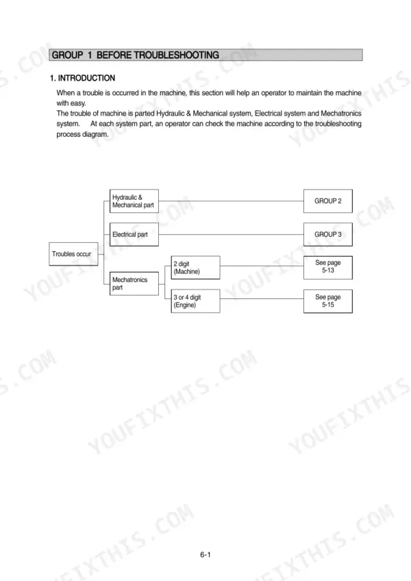
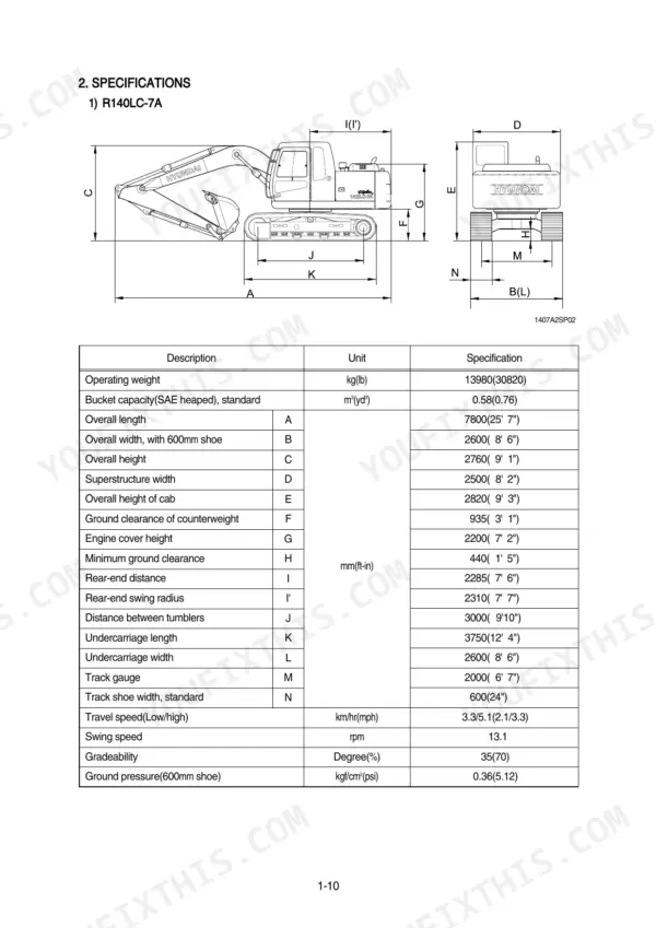
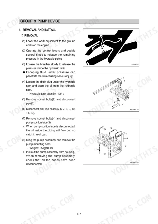
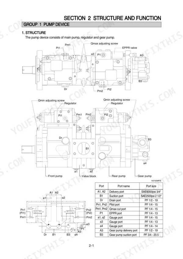
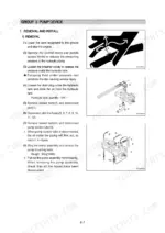
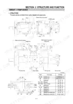
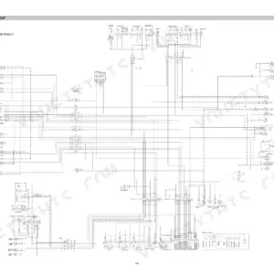
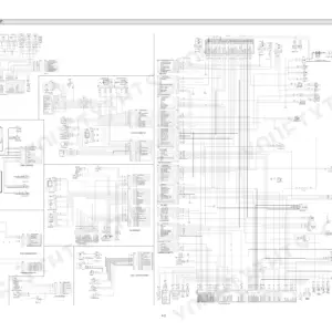
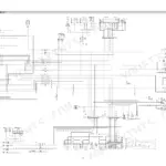
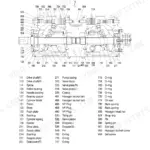
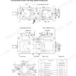
All 495 pages of this Hyundai R140LC-7A, R140LCD-7A, R140LCM-7A service manual PDF cover one job: putting your R140-7A hydraulic excavator back to work. You get full hydraulic schematics tracing the main and pilot circuits through single and combined operation, wiring diagrams with connector pinouts and component locations, and a thick troubleshooting section spanning hydraulic, electrical, and mechatronics faults. Step-by-step teardowns walk you through the pump device, main control valve, swing and travel motors, RCV levers, turning joint, and undercarriage. Torque the swing motor mounting bolts to 29.6 ± 3.2 kgf·m and set the main relief valve at 8 to 9 kgf·m (57.8 to 65.1 lbf·ft). A dead travel motor doesn't wait for forum answers. This PDF is bookmarked with a live text layer; search the spec, jump to the page, get back in the cab.
What's Inside This Hyundai R140LC-7A, R140LCD-7A, R140LCM-7A Manual
| System | Pages | Key Topics |
|---|---|---|
| General | 11-54 | Safety Hints, Specifications |
| Structure and Function | 55-130 | Pump Device, Main Control Valve, Swing Device, Travel Device, Rcv Lever, Rcv Pedal |
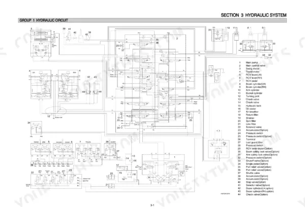
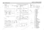
| Hydraulic System | 131-164 | Hydraulic Circuit, Main Circuit, Pilot Circuit, Single Operation, Combined Operation |
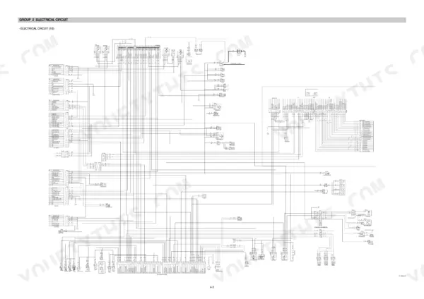
| Electrical System | 165-212 | Component Location, Electrical Circuit, Electrical Component Specification, Connectors |
| Mechatronics System | 213-235 | Outline, Mode Selection System, Automatic Deceleration System, Power Boost System, Travel Speed Control System, Automatic Warming Up Function, Engine Overheat Prevention Function |
| Maintenance Standard | 286-320 | Operational Performance Test, Major Components, Track and Work Equipment |
| Disassembly and Assembly | 321-481 | Precaution, Tightening Torque, Pump Device, Main Control Valve, Swing Device, Travel Device, Rcv Lever, Turning Joint |
| Component Mounting Torque | 482-495 | Introduction Guide, Engine System, Electric System, Undercarriage, Structure, Work Equipment |
Quick Reference Specifications
| Specification | Value | Page |
|---|---|---|
| All Models | ||
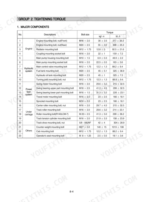
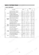
| Swing motor mounting bolt | 29.6 ± 3.2 kgf·m | p. 326 |
| Carrier roller mounting bolt, nut | 29.7 ± 4.5 kgf·m | p. 326 |
| Track roller mounting bolt | 29.6 ± 3.2 kgf·m | p. 326 |
| Main relief valve tightening torque | 8~9 kgf·m (57.8~65.1 lbf·ft) | p. 362 |
| Overload relief valve tightening torque | 8~9 kgf·m (57.8~65.1 lbf·ft) | p. 362 |
| Hexagon socket bolt (343) | 25.7 ± 4.0 kgf·m (186 ± 28.9 lbf·ft) | p. 387 |
| Tightening torque for turning joint assembly mounting bolt | 12 ± 1.3 kgf·m (88 ± 9.4 lb·ft) | p. 445 |
| Socket head bolt (Bucket cylinder) torque | 23.0 ± 2.0 kgf·m (166 ± 14.5 lbf·ft) | p. 458 |
| Socket head bolt (Boom cylinder) torque | 23.0 ± 2.0 kgf·m (166 ± 14.5 lbf·ft) | p. 458 |
| R140LC-7A | ||
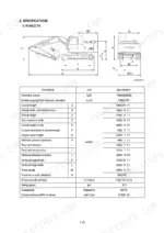
| Operating Weight, R140LC-7A | 13980 kg | p. 21 |
| R140LC-7A, 2-PIECE BOOM | ||
| Operating Weight (R140LC-7A, 2-PIECE BOOM) | 13980 kg | p. 22 |
| R140LCD-7A | ||
| Operating Weight, R140LCD-7A | 14800 kg | p. 23 |
Hyundai R140LC-7A, R140LCD-7A, R140LCM-7A Common Problems This Manual Covers
Hyundai R140LC-7A all hydraulic functions weak, boom and arm slow, low pressure on every circuit
Check hydraulic oil level and pull the suction strainer before condemning the pump. Tee a gauge into the main circuit and test relief pressure against the 330 kgf/cm2 standard setting on page 141; power boost should reach 360 kgf/cm2. If low, adjust or replace the main relief valve and torque it to 8~9 kgf·m with a 32 mm spanner.
Manual Section: Hydraulic and Mechanical System Troubleshooting p. 141Boom or arm drifts down with controls in neutral, bucket creeps under load
Test each cylinder for internal leakage: curl the bucket, shut the engine off, and watch the rod. If it creeps, reseal that cylinder. On reassembly torque the piston and lock nut to the values in the cylinder tightening-torque table on page 458. If the cylinders hold, suspect control valve spool leakage or a relief opening below spec.
Manual Section: Disassembly and Assembly p. 458Swing will not start or overshoots and does not stop cleanly, error code 24 on cluster
Read the cluster and match codes against the table on page 226; the table names the circuit behind each code, including the swing priority solenoid. Check the connector and harness continuity before buying a solenoid. If the swing motor comes off to reach the brake release valve, torque the mounting bolts to 29.6 ± 3.2 kgf·m.
Manual Section: Error Codes Table p. 226Hydraulic pump growling, oil foaming in reservoir, jerky response after cold start
Check the reservoir oil level on level ground and top up before chasing anything else. Clean or replace the suction strainer and the reservoir breather, then tighten every suction line fitting; a pinhole air leak foams oil fast. After the noise stops, confirm standard relief pressure still reaches 330 kgf/cm2 as listed on page 141.
Manual Section: Hydraulic and Mechanical System Troubleshooting p. 306Travel weak or dead on one side, machine pulls toward one track
Swap the front and rear pump discharge hoses; if the weak side switches, the fault is pump side, not the travel motor. Check the travel spool for sticking and test both travel relief valves. When refitting an overload relief cartridge, torque it to 8~9 kgf·m with a 32 mm spanner as shown on page 362.
Manual Section: Hydraulic and Mechanical System Troubleshooting p. 362Frequently Asked Questions
How do I troubleshoot a Hyundai R140LC-7A that will not start?
To troubleshoot an engine that will not start, first check the battery charge and specific gravity (minimum 1.28). Then, check the operation of the start motor, the start relay, and the anti-restart relay (CR-5). Detailed diagnostic steps, including voltage checks at the start switch and starter magnet coil, are provided on page 271. p. 271
How do I check the cluster or mode selection system on a Hyundai R140LC-7A?
If the cluster or mode selection system malfunctions, check the connection between CN-51 (29) and CN-50 (10), or CN-50 (30) and CN-5 (11). Ensure all related connectors are properly inserted. If the problem persists, check the fuse No. 11 (CPU). p. 280
What are the replacement specifications for the Main relief valve?
The main relief valve should be replaced if it is damaged or if the contacting face of the valve seat or poppet is damaged. When replacing, the tightening torque for the main relief valve is 8-9 kgf·m (57.8-65.1 lbf·ft) using a 32mm spanner. p. 362
What is the standard engine oil capacity for the R140LC-7A engine?
The engine oil capacity for the Mitsubishi D04FD-TAA engine is 18.5 liters (4.9 U.S. gal). p. 50
What is the tightening torque for the track shoe mounting bolts?
The track shoe mounting bolts and nuts for the R140LC-7A should be tightened to 42 ± 4 kgf·m (304 ± 28.9 lbf·ft). p. 325
Will this Hyundai R140LC-7A Service Manual download right away?
Straight to your device: 495 pages of searchable Service Manual, downloadable the moment payment goes through.
Can I print just the pages I need from this Hyundai R140LC-7A manual?
Yes. Print the pages or sections you need for your own shop use. Any standard printer works.









Reviews
There are no reviews yet.