
Part of the Hyundai Repair Manuals.
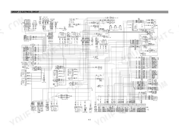
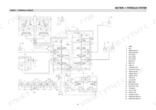
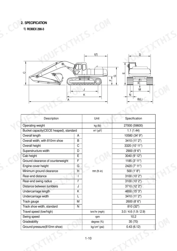
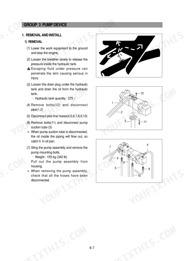
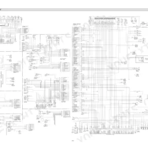
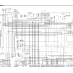
Wrenching on a Hyundai R290LC-3, R290NLC-3, or R290-3? This 475-page service manual PDF covers the whole crawler excavator family, from the pump device and main control valve to the swing and travel drives. Inside: hydraulic circuit schematics with main and pilot routing, electrical wiring diagrams with component locations, exploded views of the major assemblies, and a full troubleshooting section for chasing faults system by system. You also get complete disassembly and assembly procedures plus operational performance tests for judging component wear before you tear anything down. The twin main pumps run 140 cc/rev each and peak at 320 kg/cm2 (4550 psi); fill the hydraulic system to 380 L, with 270 L in the tank. Your excavator earns nothing parked. Bookmarked chapters and a keyword-searchable text layer mean you find the spec, grab the wrench, and get back on the sticks.
What's Inside This Hyundai R290LC-3, R290NLC-3, R290-3 Manual
| System | Pages | Key Topics |
|---|---|---|
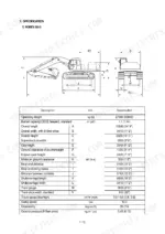
| General | 9-37 | Safety, Specifications |
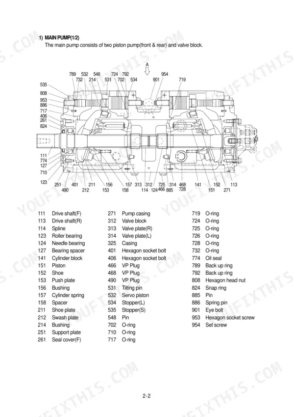
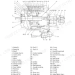
| Structure and Function | 38-116 | Pump Device, Main Control Valve, Swing Device, Travel Device |
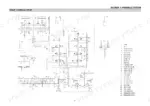
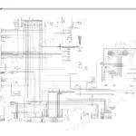
| Hydraulic System | 117-145 | Hydraulic Circuit, Main Circuit, Pilot Circuit |
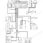
| Electrical System | 146-204 | Component Location, Electrical Circuit, Power Circuit |
| Mechatronics System | 205-222 | Operation of Capo System, Engine Control System |
| Maintenance Standard | 283-322 | Operational Performance Test, Major Component |
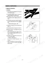
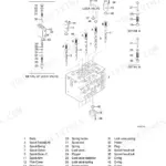
| Disassembly and Assembly | 323-475 | Precautions, Pump Device, Main Control Valve, Swing Device, Travel Device, Work Equipment |
Quick Reference Specifications
| Specification | Value | Page |
|---|---|---|
| Hydraulic tank capacity | 270 L (71.3 U.S. gal) | p. 37 |
| Hydraulic system capacity | 380 L (100.3 U.S. gal) | p. 37 |
| Pilot pump maximum pressure | 40 kg/cm2 (570 psi) | p. 32 |
| Main pump capacity | 2 x 140 cc/rev | p. 31 |
| Main pump maximum pressure | 320 kg/cm2 (4550 psi) | p. 31 |
| Secondary pressure | 5 to 19 kgf/cm² | p. 104 |
| Relief valve pressure | 40kg/cm2 | p. 121 |
| RCV Lever push rod wear limit | 1 mm | p. 313 |
| Swing bearing upper part mounting bolt | 97.8±10 kgf·m (707.4±72.3 lbf·ft) | p. 327 |
| Swing bearing lower part mounting bolt | 97.8±10 kgf·m (707.4±72.3 lbf·ft) | p. 327 |
| Carrier roller mounting bolt | 21.0±2.3 kgf·m (151.9±16.6 lbf·ft) | p. 327 |
| Track roller mounting bolt | 54.7±6.0 kgf·m (395.6±43.4 lbf·ft) | p. 327 |
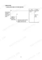
Hyundai R290LC-3, R290NLC-3, R290-3 Common Problems This Manual Covers
Hyundai R290-3 all hydraulic functions weak and slow, pump whining at operating temperature
Check hydraulic oil level with the bucket grounded; the tank holds 270 L (71.3 U.S. gal) per page 37. Drain and inspect the suction filter for debris, then bleed air from the pump housing. Verify main pump pressure reaches 320 kg/cm2 (4550 psi); low readings point to worn rotating group parts.
Manual Section: Hydraulic System Troubleshooting p. 37Joystick inputs feel dead or laggy, attachments barely move until engine is revved high
Test pilot pressure at the remote control valve supply line; the pilot relief is set at 40 kg/cm2 (570 psi), shown on page 121. Inspect pilot hoses for kinks and internal delamination. Measure the RCV lever push rods against the 1 mm wear limit on page 313 and replace any rod worn past it.
Manual Section: Hydraulic System p. 121Grinding rattle between engine and pump at idle, machine stalls under load
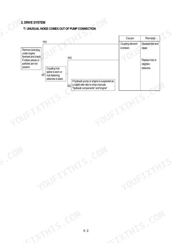
Remove the pump access cover and inspect the coupling element for shredded rubber and loose hardware. Replace the element if teeth are chipped, then torque the coupling mounting socket bolts to 6.9±1.4 kgf·m (50±10 lbf·ft) from the table on page 326. Check pump shaft splines for fretting before reassembly.
Manual Section: Drive System Troubleshooting p. 326Swing drifts past target and creeps on slopes, upper structure feels loose
Verify swing motor relief pressure against the 240 kg/cm2 spec on page 34; replace the relief cartridge if it tests low. Check the swing bearing for movement and retorque upper and lower mounting bolts to 97.8±10 kgf·m (707.4±72.3 lbf·ft) per page 326. Inspect bearing grease for metal flakes while you are there.
Manual Section: Swing System Troubleshooting p. 34Tracks loose and slapping the frame, shoe bolts backing out on rough ground
Adjust track sag with the grease tension cylinder before chasing hardware. Retorque track shoe bolts to 79±4.0 kgf·m (571±29 lbf·ft) and track roller bolts to 54.7±6.0 kgf·m, both from the torque table on page 326. Replace any bolt that has stretched; a rolled thread will not hold torque twice.
Manual Section: Disassembly and Assembly p. 326Frequently Asked Questions
What are the torque specifications for the track shoe mounting bolts and nuts on the R290LC-3?
The tightening torque for the track shoe mounting bolts and nuts on the R290LC-3 is 79 ± 4.0 kgf·m (571 ± 29 lbf·ft). p. 326
What are the torque specifications for the swing bearing mounting bolts on the R290LC-3?
The tightening torque for the swing bearing upper and lower part mounting bolts is 97.8 ± 10 kgf·m (707.4 ± 72.3 lbf·ft). p. 326
What is the replacement interval for the gear oil in the travel reduction gear?
The gear oil should be replaced for the first time at 500 hours, and every 2000 hours thereafter. After disassembling, it must be filled with new oil without fail. p. 312
What is the standard clearance for the track roller side clearance?
The standard side clearance for the track roller is 0.2 to 0.6 mm, with a repair limit of 1.5 mm. p. 317
What is the standard torque for the main pump mounting socket bolts?
The standard tightening torque for the main pump mounting socket bolts (M20 x 2.5) is 42.0 ± 4.5 kgf·m (303.8 ± 32.5 lbf·ft). p. 326
What exactly do I receive with this Service Manual?
Delivery is instant: a 475-page searchable PDF is yours the second checkout clears. Laptop, tablet, or phone, all fine.
Can I print specific sections of this Service Manual?
Yes. Print a chapter or just the pages for the job at hand, for use in your own shop. Any home or office printer works.






Reviews
There are no reviews yet.