
Part of the Hyundai Repair Manuals.
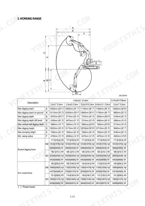
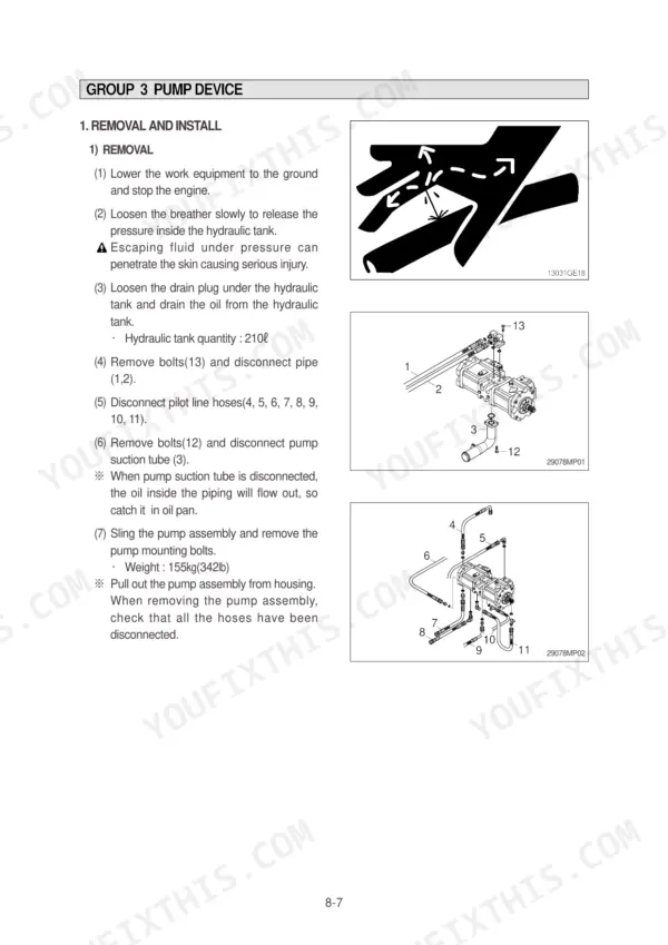
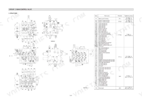
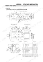
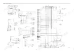
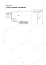
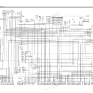
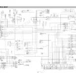
Every one of the 533 pages in this Hyundai R320LC-7 Service Manual PDF exists for one reason: getting your R320LC-7 hydraulic excavator digging again. You get full hydraulic schematics tracing the main and pilot circuits through single and combined operation, plus wiring diagrams with connector pinouts and component locations for the entire electrical system. Open to the troubleshooting section and chase hydraulic, electrical, and mechatronics faults step by step, then follow complete disassembly and assembly procedures for the pump, main control valve, swing and travel devices. Set the main relief valve to 330 kgf/cm2 (4690 psi) and the pilot relief to 35 kgf/cm2, straight from the factory tables. A weak boom is a spec problem, not a mystery. Bookmarked with a real text layer: search a spec, jump to the section, fix the machine.
What's Inside This Hyundai R320LC-7 Manual
| System | Pages | Key Topics |
|---|---|---|
| General | 11-35 | Safety Hints, Specifications |
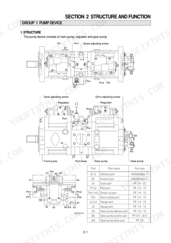
| Structure and Function | 36-130 | Pump Device, Main Control Valve, Swing Device, Travel Device, Rcv Lever, Rcv Pedal |
| Hydraulic System | 131-162 | Hydraulic Circuit, Main Circuit, Pilot Circuit, Single Operation, Combined Operation |
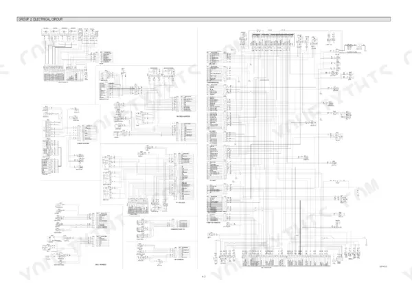
| Electrical System | 163-207 | Component Location, Electrical Circuit, Electrical Component Specification, Connectors |
| Mechatronics System | 208-245 | Outline, Mode Selection System, Automatic Deceleration System, Power Boost System, Travel Speed Control System, Automatic Warming Up Function, Engine Overheat Prevention Function |
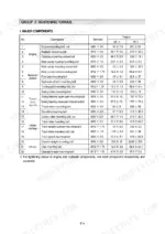
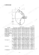
| Maintenance Standard | 303-339 | Operational Performance Test, Major Components, Track and Work Equipment |
| Disassembly and Assembly | 340-517 | Precaution, Tightening Torque, Pump Device, Main Control Valve, Swing Device, Travel Device, Rcv Lever, Turning Joint |
| Component Mounting Torque | 518-533 | Introduction Guide, Engine System, Electric System, Undercarriage, Structure, Work Equipment |
Quick Reference Specifications
| Specification | Value | Page |
|---|---|---|
| Main relief valve pressure | 330kgf/cm2 (4690psi) | p. 32 |
| Overload relief valve pressure | 390kgf/cm2 (5550psi) | p. 32 |
| Boom cylinder Bore dia x Rod dia x Stroke | Ø150 x Ø105 x 1480mm | p. 33 |
| Arm cylinder Bore dia x Rod dia x Stroke | Ø160 x Ø110 x 1685mm | p. 33 |
| Pilot relief valve setting pressure | 35kgf/cm2 | p. 136 |
| Track shoe mounting bolt, nut | 115 ± 5.0 kgf·m | p. 527 |
| Carrier roller mounting bolt, nut | 29.7 ± 4.5 kgf·m | p. 527 |
| Track roller mounting bolt | 57.9 ± 8.6 kgf·m | p. 528 |
| Main relief valve tightening torque | 7~8 kgf·m (50.6~57.8 lbf·ft) | p. 381 |
| Port relief valve tightening torque | 7~8 kgf·m (50.6~57.8 lbf·ft) | p. 381 |
| Socket head bolt, boom cylinder (M18) | 46.0 ± 5.0 kgf·m (333 ± 36.2 lbf·ft) | p. 494 |
| Operating Weight | 32200 kg | p. 21 |
Hyundai R320LC-7 Common Problems This Manual Covers
Hyundai R320LC-7 loses hydraulic pressure, all functions weak, boom and travel slow under load
Check main relief valve pressure with a gauge on the pump test port; spec is 330 kgf/cm2 (4690 psi). Work the low-power troubleshooting steps starting before condemning the pump. If the valve is bad, replace the cartridge and torque it to 7~8 kgf·m per the chart on page 527.
Manual Section: Hydraulic and Mechanical System Troubleshooting p. 250Boom, bucket, and travel on one side underpowered while opposite side works normally
Test each pump circuit separately to isolate the weak side. Verify that side's relief setting reaches 330 kgf/cm2 (4690 psi); one misadjusted side relief drops boom, bucket, and one travel motor together. Follow the diagnostic chart, then adjust or replace the valve and torque it to 7~8 kgf·m.
Manual Section: Hydraulic and Mechanical System Troubleshooting p. 250Boom or arm creeps down slowly with control levers in neutral, machine parked
Swap the suspect port relief valve with its neighbor; if the drift follows the valve, replace it and torque to 7~8 kgf·m. Overload relief should open at 390 kgf/cm2 (5550 psi). If drift stays put, reseal the cylinder and torque the piston assembly to 150 ± 15.0 kgf·m during rebuild, page 500.
Manual Section: Boom, Arm, and Bucket Cylinder Troubleshooting p. 500Hydraulic system overheats, response turns sluggish and noisy after a few hours of digging
Check hydraulic oil level and condition first; milky or dark oil means water or heat damage, so drain and refill. Replace clogged return and pilot filters, then verify pilot pressure holds 35 kgf/cm2. Blow out the oil cooler fins and run the overheating diagnostics before blaming the pump.
Manual Section: Hydraulic and Mechanical System Troubleshooting p. 250Track sags and jumps the idler during travel, shoe bolts keep working loose
Measure track sag between the carrier roller and idler, then adjust tension with the grease fitting on the tension cylinder. Retorque loose track shoe bolts to 115 ± 5.0 kgf·m using the chart on page 527, and check track roller bolts at 57.9 ± 8.6 kgf·m before they shear.
Manual Section: Undercarriage Troubleshooting p. 527Frequently Asked Questions
How do I clear all recorded error codes on the Hyundai R320LC-7 monitor?
To clear all recorded error codes, select the recorded error (TIME Er) display mode on the cluster. Press the engine and select switch at the same time for 2 seconds or more. The cluster display will change to 'TIME Er : 00', indicating that the CPU controller has deleted all recorded error codes from the memory. p. 220
How do I check the fault codes on a Hyundai R320LC-7?
To check fault codes, touch the SELECT switch 2 times while pressing the BUZZER STOP switch on the cluster to enter the error display mode. The cluster will display real-time error codes received from the CPU controller. If there are more than two error codes, you can view each one by pressing the up and down arrow switches. p. 220
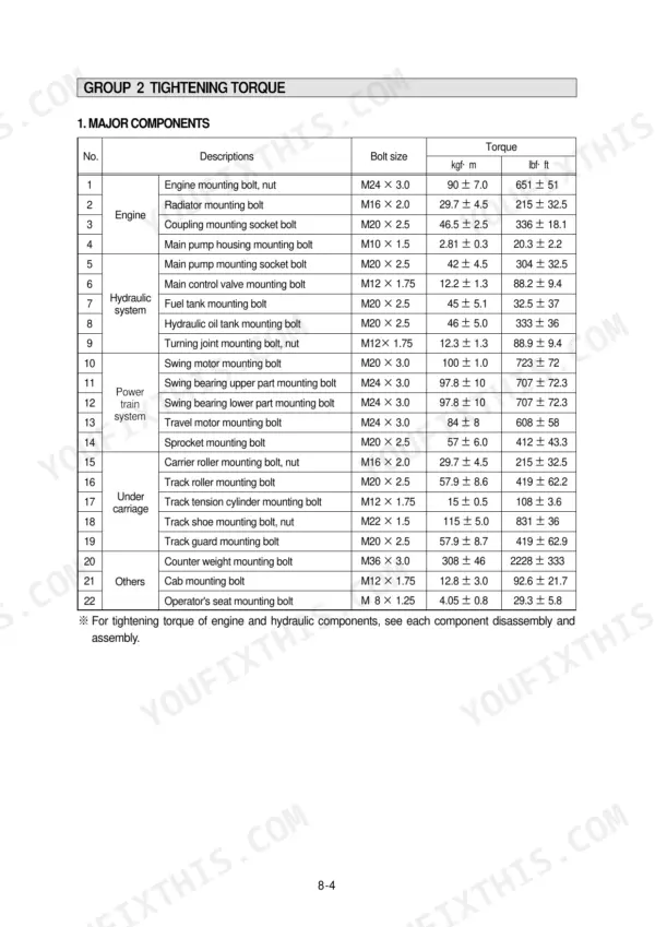
What is the tightening torque for the engine mounting bolts on the R320LC-7?
The tightening torque for the M24 x 3.0 engine mounting bolts and nuts is 90 ± 7.0 kgf·m (651 ± 51 lbf·ft). p. 344
What is the procedure to bleed air from the hydraulic pump after installation?
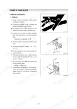
After installing the pump, remove the two air vent plugs. Tighten the plugs lightly, start the engine, and run it at low idling until oil comes out from the plugs. Finally, tighten the plugs fully. p. 348
What is the standard engine speed for the R320LC-7 in H mode?
The standard engine speed for the R320LC-7 in H mode is 1850 ± 50 rpm, measured with the accel dial at the 10 (Max) position. p. 307
What do I get after purchasing this Hyundai R320LC-7 manual?
This is a 533-page searchable PDF ready for immediate download. Works on any device, so pull it up on your phone while you're under the hood. No shipping, no waiting.
Am I able to print pages from this Hyundai R320LC-7 manual?
Yes. Print a chapter or just the pages for the job at hand, for use in your own shop. Any home or office printer works.







Reviews
There are no reviews yet.