

Part of the Hyundai Repair Manuals.
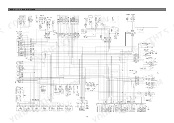
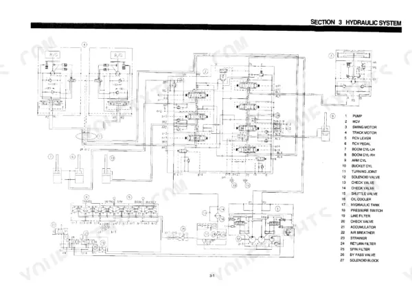
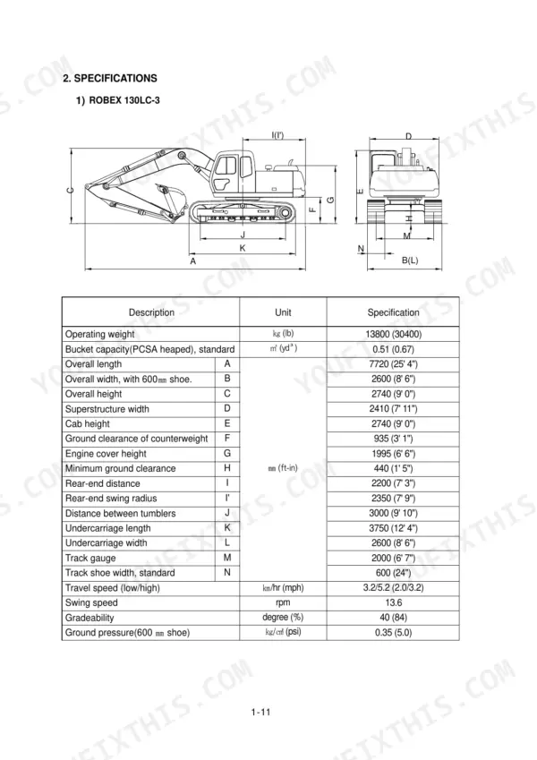
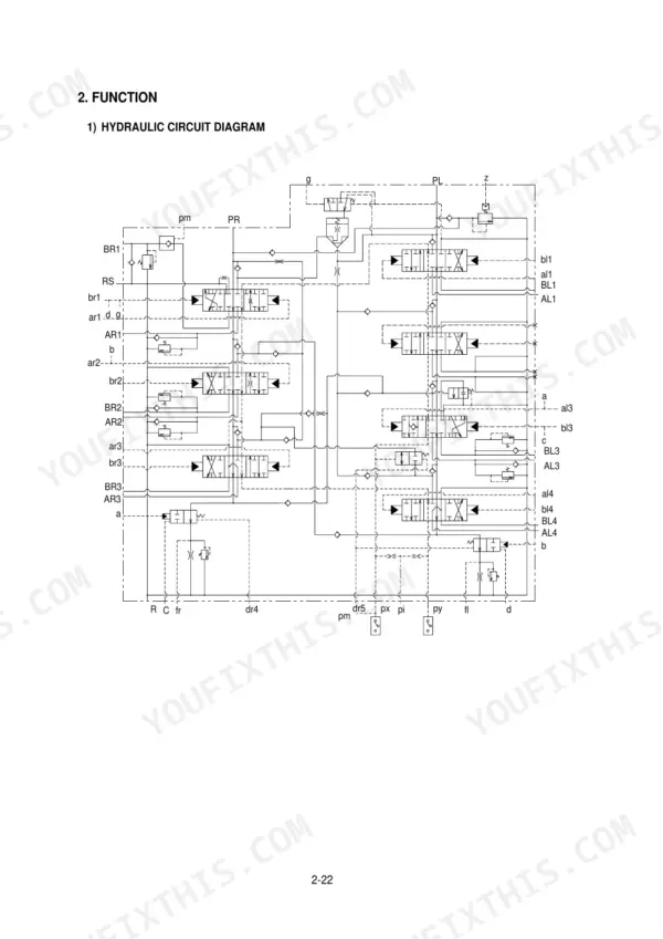
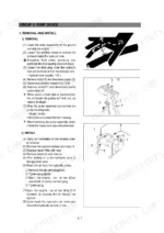
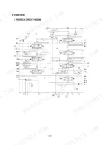
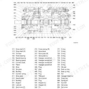
All 464 pages of this Hyundai Robex 130LC-3, 130LCM-3 shop manual PDF focus on one job: putting your hydraulic excavator back to factory spec, from pump device to turning joint. You get hydraulic schematics tracing the main and pilot circuits, wiring diagrams with connector pinouts and component locations, and a full troubleshooting section covering the swing, travel, and attachment systems. Disassembly and assembly procedures walk through the pump, swing device, travel device, and main control valve, with tightening torque tables right where you need them. Test the auto idle pressure switch against its 10 kg/cm2 contact rating, and verify charging from the 24V, 60 amp alternator before condemning those twin 12V, 120 Ah batteries. Chasing an electrical fault without the factory diagram is a wasted afternoon. Bookmarked with a live text layer: type the spec, land on the page, get back on the sticks.
What's Inside This Hyundai ROBEX 130LC-3, ROBEX 130LCM-3 Manual
| System | Pages | Key Topics |
|---|---|---|
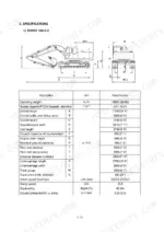
| General | 9-33 | Safety, Specifications |
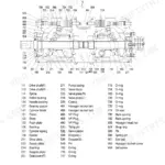
| Structure and Function | 34-120 | Pump Device, Main Control Valve, Swing Device, Travel Device, Rcv Lever |
| Hydraulic System | 121-141 | Main Circuit, Pilot Circuit, Single Operation |
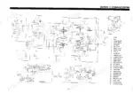
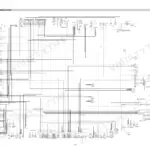
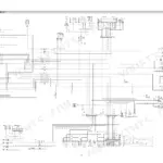
| Electrical System | 142-191 | Component Location, Electrical Circuit, Monitoring System, Electrical Component Specification, Connectors |
| Mechatronics System | 192-203 | Outline, Operation of Capo System, Engine Control System, EPPR Valve, Prolix Switch |
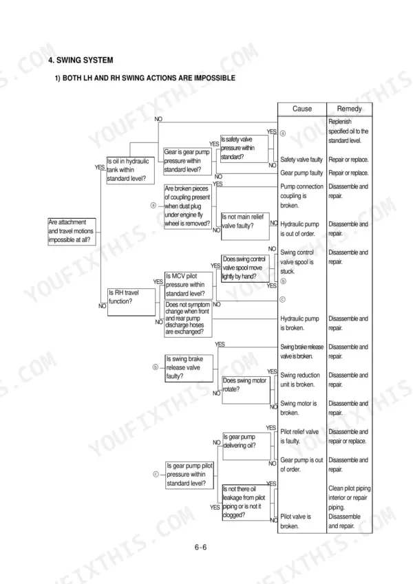
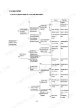
| Troubleshooting | 204-265 | Hydraulic and Mechanical System, Swing System, Travel System, Attachment System |
| Maintenance Standard | 266-307 | Operational Performance Test, Major Component, Track and Work Equipment |
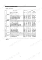
| Disassembly and Assembly | 308-464 | Precautions, Tightening Torque, Pump Device, Swing Device, Travel Device, Turning Joint |
Quick Reference Specifications
| Specification | Value | Page |
|---|---|---|
| Alternator | DAC HC60(24V-60AMP) | p. 31 |
| Battery | 2 x 12V x 120 Ah | p. 31 |
| Voltage | 10 ~ 12.5V | p. 145 |
| Fusible link | 60A | p. 171 |
| Pressure switch (for auto idle) contact | 10 kg/cm2 | p. 171 |
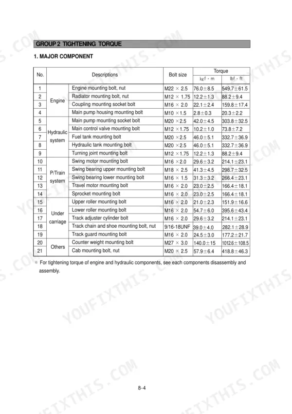
| Upper roller mounting bolt | 21.0 ± 2.3 kgf·m | p. 312 |
| Lower roller mounting bolt | 54.7 ± 6.0 kgf·m | p. 312 |
| Socket head bolt (arm cylinder) torque | 32 ± 3.2 kgf·m (231.5 ± 23.1 lbf·ft) | p. 422 |
| Tightening torque for cylinder head assembly to piston rod | 100 ± 10 kgf·m (723 ± 72 lbf·ft) | p. 428 |
| Engine Oil Quantity | 11 L | p. 31 |
| Main Pump Rated Oil Flow | 2 x 130 L/min | p. 31 |
| Engine High Idling Speed | 2350 + 50 rpm | p. 31 |
Hyundai ROBEX 130LC-3, ROBEX 130LCM-3 Common Problems This Manual Covers
Hyundai Robex 130LC-3 hydraulic functions slow and weak, oil looks milky, bucket barely lifts
Check the hydraulic oil first; milky or cloudy oil means water contamination or air pulling in at the suction line. Drain and refill with clean oil, replace the return filter, and clean the suction strainer. Then test the main relief valve against the pressure spec in the General section before condemning the pump.
Manual Section: Hydraulic System Troubleshooting p. 204Machine will not start or electrical systems cut in and out during operation
Test battery voltage at the terminals; readings below the 10 to 12.5V range shown on page 145 point to charging or battery trouble. Check the 60A fusible link on page 171, then clean and tighten every ground strap and battery terminal. Load-test both 12V 120Ah batteries and trace open circuits with the wiring diagram on page 144.
Manual Section: Electrical System Troubleshooting p. 145Engine oil pressure warning lamp stays on at idle after an oil change
Check the oil level first and top up to the 11 L capacity listed on page 31. Replace the oil filter cartridge if it is restricted. If the lamp stays lit with good oil and filter, test the oil pressure switch against the electrical component specification; a failed switch grounds the lamp constantly.
Manual Section: Electrical System Troubleshooting p. 31Upper structure swings slowly, drifts on slopes, or will not hold position when parked
Verify hydraulic oil level and pilot pressure to the swing motor before condemning hard parts. Work through the swing troubleshooting procedures starting, and confirm the main relief valve holds the pressure given in the General specifications. Inspect the swing brake release circuit for a sticking solenoid valve while you are in there.
Manual Section: Swing System Troubleshooting p. 204Track shoe bolts loosen repeatedly, rollers rattle, track sags after a few hundred hours
Torque track chain and shoe bolts to the value in the torque table on page 312. Retorque upper roller mounting bolts to 21.0 ± 2.3 kgf·m and lower roller bolts to 54.7 ± 6.0 kgf·m. Check track tension and roller wear against the maintenance standard section starting on page 266.
Manual Section: Disassembly and Assembly p. 312Frequently Asked Questions
What are the replacement specifications for the hydraulic return filter?
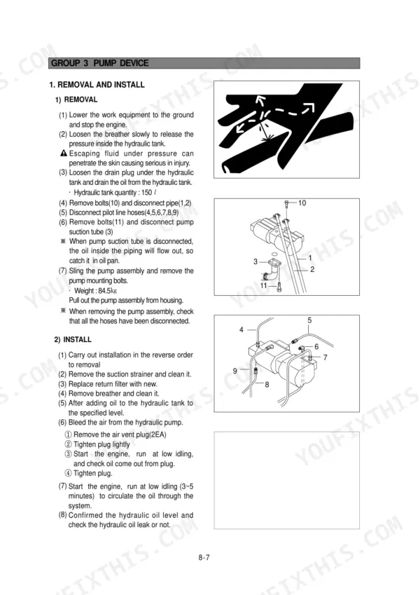
The hydraulic return filter should be replaced with a new one during the installation procedure after maintenance. When the filter element is clogged, the bypass relief valve opens at a differential pressure of 1.5 kg/cm² (21 psi). p. 123
What is the tightening torque for the main pump mounting socket bolt?
The tightening torque for the main pump mounting socket bolt (M20 x 2.5) is 42.0 ± 4.5 kgf·m (303.8 ± 32.5 lbf·ft). p. 311
What is the standard engine speed for the R130LC-3 in H-mode?
The standard engine speed for the R130LC-3 in H-mode is 2350 ± 50 rpm. p. 271
How do I bleed the air from the hydraulic pump after installation?
To bleed the air from the hydraulic pump, remove the air vent plug (2EA), tighten the plug lightly, start the engine at low idling, and check that oil comes out from the plug. Once oil flows, tighten the plug fully. p. 314
What is the standard clearance for the track roller side clearance?
The standard clearance for the track roller side clearance is 0.2 to 0.6 mm, with a clearance limit of 1.5 mm. p. 302
Do I get instant access to this Hyundai Robex 130LC-3 Shop Manual?
Straight to your device: 464 pages of searchable Shop Manual, downloadable the moment payment goes through.
Does this Hyundai Robex 130LC-3 manual allow printing?
Yes. It prints from any PDF reader, so run off the pages you need for your own repair work.







Reviews
There are no reviews yet.