
Part of the Hyundai Repair Manuals.
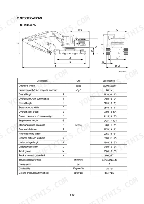
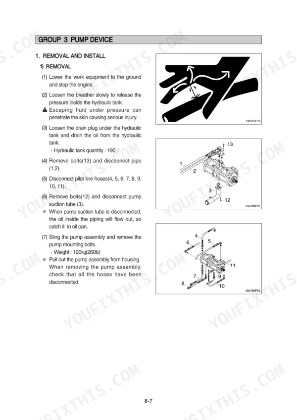
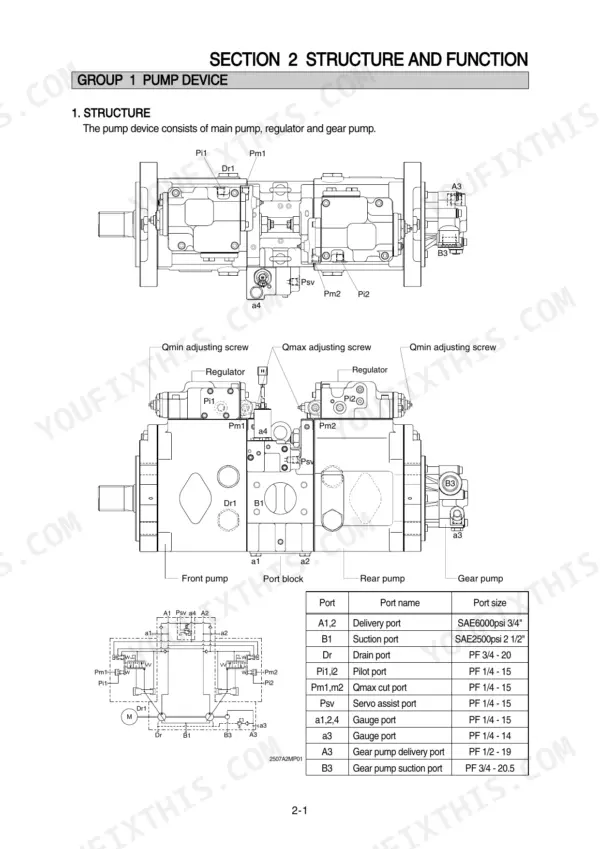
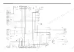
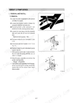
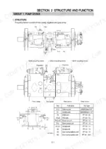
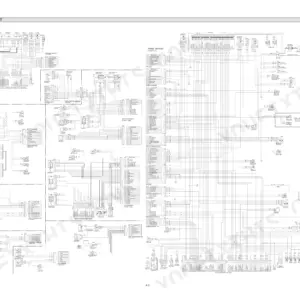
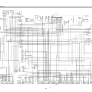
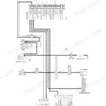
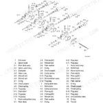
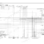
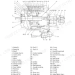
Every one of the 496 pages in this Hyundai R250LC-7A, R250NLC-7A Service Manual PDF targets one machine family: the R250-7A hydraulic excavator, including the High Walker variant. You get full electrical circuit diagrams with connector pinouts, hydraulic schematics tracing the main and pilot circuits through single and combined operation, and a self-diagnostic section that decodes the mechatronics error codes on your monitor panel. Step-by-step teardown procedures walk you through the pump device, main control valve, swing and travel drives, and boom, arm, and bucket cylinders, all backed by a dedicated component mounting torque chapter. Set the pilot relief valve at 35 kgf/cm2 and pull PF 1 hydraulic ports to 20~25 kgf·m (115~180 lbf·ft). No more chasing a swing fault with a test light and a hunch. Bookmarked, keyword-searchable, and readable on any device: download it and walk straight to the machine.
What's Inside This Hyundai R250LC-7A, R250NLC-7A Manual
| System | Pages | Key Topics |
|---|---|---|
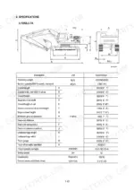
| General | 11-45 | Safety Hints, Specifications |
| Structure and Function | 46-126 | Pump Device, Main Control Valve, Swing Device, Travel Device, Rcv Lever, Rcv Pedal |
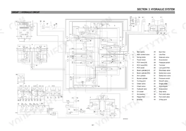
| Hydraulic System | 127-158 | Hydraulic Circuit, Main Circuit, Pilot Circuit, Single Operation, Combined Operation |
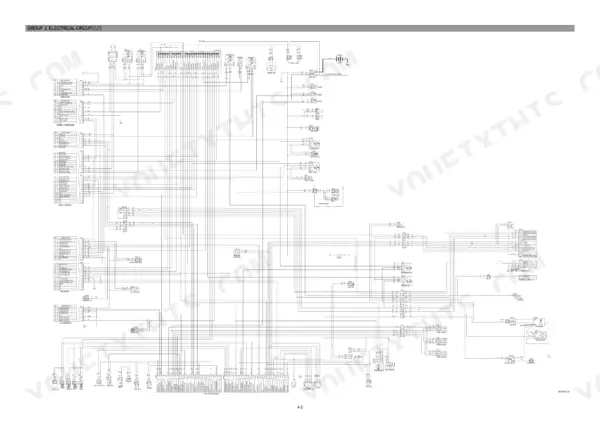
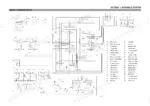
| Electrical System | 159-206 | Component Location, Electrical Circuit, Electrical Component Specification, Connectors |
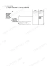
| Mechatronics System | 207-236 | Outline, Mode Selection System, Self-Diagnostic System |
| Maintenance Standard | 287-323 | Operational Performance Test, Major Components, Track and Work Equipment |
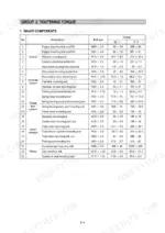
| Disassembly and Assembly | 324-481 | Precaution, Tightening Torque, Pump Device, Main Control Valve, Swing Device, Travel Device, Rcv Lever, Turning Joint |
| Component Mounting Torque | 482-496 | Introduction Guide, Engine System, Electric System, Undercarriage, Structure, Work Equipment |
Quick Reference Specifications
| Specification | Value | Page |
|---|---|---|
| Flow control starting pressure change amount | +1.3 kgf/cm2 | p. 58 |
| Tightening torque for PF 1 port | 20~25 kgf·m (115~180 lbf·ft) | p. 67 |
| Tightening torque for PF 3/4 port | 15~18 kgf·m (109~130 lbf·ft) | p. 67 |
| Pilot relief valve pressure | 35 kgf/cm2 | p. 132 |
| Bypass relief valve opening pressure (full-flow filter) | 1.5 kgf/cm2 | p. 130 |
| Bypass check valve opening pressure (return circuit) | 1.5 kgf/cm2 | p. 131 |
| Standard pressure for Boom, Arm, Bucket | 330(360)±10 kgf/cm² | p. 307 |
| Standard pressure for Travel | 330±10 kgf/cm² | p. 307 |
| Port relief v/v setting for Boom, Arm, Bucket | 390±10 kgf/cm² | p. 307 |
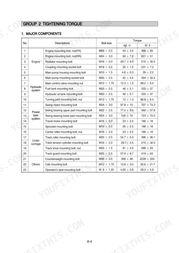
| Track shoe mounting bolt, nut | 81 ± 4.0 kgf·m (586 ± 29 lbf·ft) | p. 329 |
| Socket head bolt (Bucket cylinder, Item 23, M22) | 63.0 ± 6.0 kgf·m (456 ± 43.4 lbf·ft) | p. 458 |
| Socket head bolt (Boom cylinder, Item 23, M22) | 63.0 ± 6.0 kgf·m (456 ± 43.4 lbf·ft) | p. 458 |
Hyundai R250LC-7A, R250NLC-7A Common Problems This Manual Covers
Hyundai R250LC-7A all hydraulic functions weak, machine cannot build normal system pressure under load
Test main pump delivery pressure with a gauge at the pump ports. Boom, arm, and bucket circuits on the R250LC-7A should read 330(360)±10 kgf/cm², per the maintenance standard on page 307. If pressure is low, remove and inspect the main relief valve for a stuck poppet, then reinstall it torqued to 7~8 kgf·m with a 32mm spanner.
Manual Section: Maintenance Standard p. 307Boom drifts down and arm creeps toward the bucket when levers sit in neutral
Check the oil port relief valves first; one opening too low lets the cylinder bleed down in neutral. Swap the suspect valve with a matching valve from another circuit and watch whether the drift follows it. Torque each port relief valve to 7~8 kgf·m (50.6~57.8 lbf·ft) on reinstall, following page 365. If drift stays put, reseal the cylinder.
Manual Section: Disassembly and Assembly p. 365All attachment functions dead or barely responding, engine runs fine, suspect pilot pressure loss
Tee a gauge into the pilot line and check pressure with the safety lever unlocked. The pilot relief valve should hold 35 kgf/cm², shown in the pilot circuit on page 132. Zero pressure points to a failed pilot pump, stuck safety solenoid, or plugged pilot line filter. Verify the solenoid clicks when you cycle the lever before tearing anything down.
Manual Section: Hydraulic System p. 132Hydraulic oil temperature warning comes on and functions slow after an hour of digging
Check hydraulic oil level and condition first; cloudy or dark oil means contamination or water. Blow out the oil cooler fins with compressed air and inspect the fan belt. Replace a plugged full-flow filter element; its bypass valve opens at just 1.5 kgf/cm², detailed on page 130, so a dirty element dumps hot unfiltered oil straight back to tank.
Manual Section: Hydraulic System p. 130Hydraulic hoses weeping at fittings, fresh oil film on boom lines after washing
Wipe the fittings dry and run the machine to pinpoint the leak; use cardboard, never your hands. Crack the connection loose, inspect the seat and O-ring for scoring, then retorque: PF 1 ports take 20~25 kgf·m and PF 3/4 ports 15~18 kgf·m per the chart on page 67. Replace any hose showing soft spots or exposed wire braid.
Manual Section: Structure and Function p. 67Frequently Asked Questions
What are the hydraulic pressure specifications for the main relief valve on a Hyundai R250LC-7A?
The main relief valve pressure for the R250LC-7A is 330 kgf/cm² (4690 psi). When the power boost function is activated, this pressure increases to 360 kgf/cm² (5120 psi). p. 42
How do I check the fault codes on a Hyundai R250LC-7A excavator?
When an abnormality occurs, the CPU controller diagnoses the problem and sends error codes to the cluster, which are then stored in memory. You can view these codes by accessing the 'Diagnosis' menu on the cluster display, where you can view current and recorded errors. p. 219
What is the tightening torque for the engine mounting bolts on a Hyundai R250LC-7A?
The tightening torque for the front engine mounting bolts (M20 x 2.5) is 55 ± 3.5 kgf·m (398 ± 25 lbf·ft), and for the rear engine mounting bolts (M24 x 3.0) it is 90 ± 7.0 kgf·m (651 ± 51 lbf·ft). p. 328
What is the procedure for bleeding air from the hydraulic pump after installation?
After installing the pump, remove the air vent plug (2EA), tighten it lightly, start the engine at low idling, and check that oil comes out from the plug. Once oil flows, tighten the plug fully and run the engine at low idling for 3 to 5 minutes to circulate the oil. p. 332
What is the standard clearance for the track roller shaft and bushing?
The standard clearance between the track roller shaft and bushing is 0.39 to 0.476 mm, with a repair limit of 2.0 mm. p. 318
How quickly can I access this Hyundai R250LC-7A manual after buying?
Delivery is instant: a 496-page searchable PDF is yours the second checkout clears. Laptop, tablet, or phone, all fine.
Is this Hyundai R250LC-7A manual print-friendly?
Yes. Printing works from any reader and any printer, for your own shop use.








Reviews
There are no reviews yet.