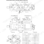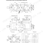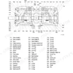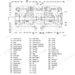



Part of the Hyundai Repair Manuals.
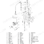
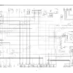
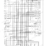
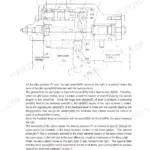
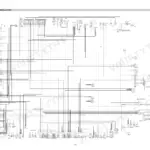
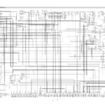
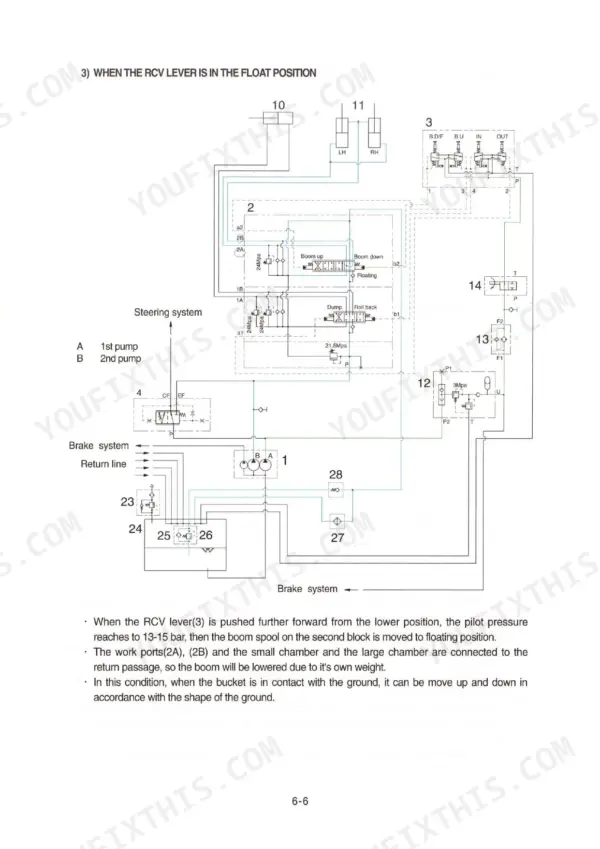
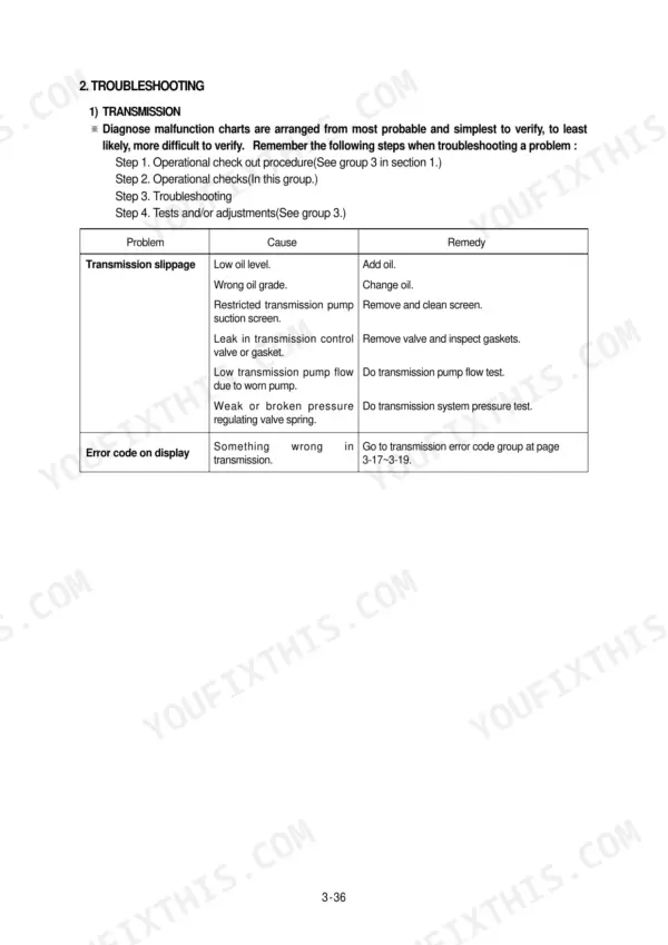
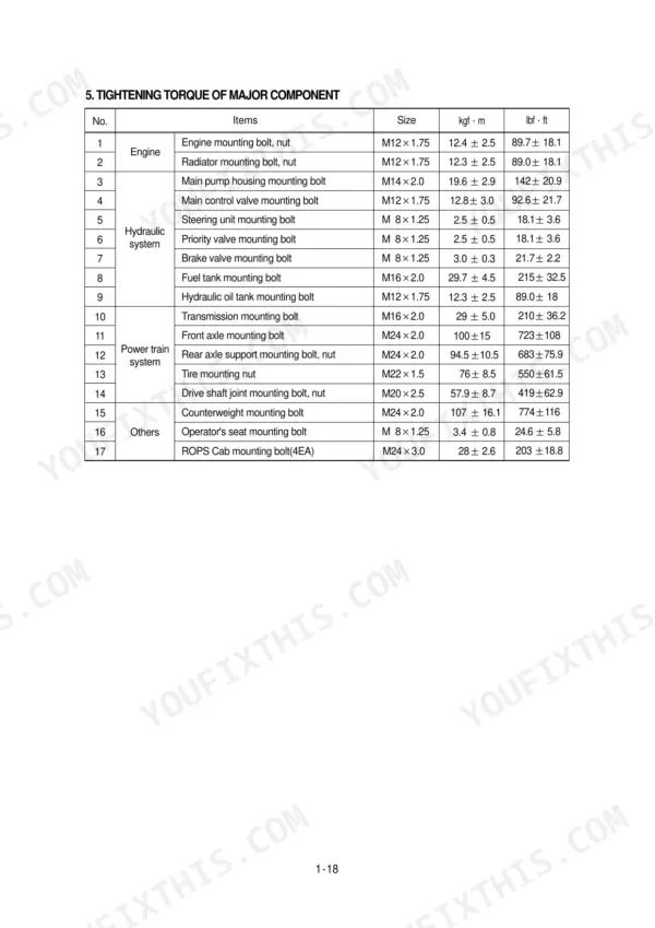
All 441 pages of this Hyundai HL730-3 Service Manual PDF focus on one machine: the HL730-3 Wheel Loader, from torque converter to bucket cylinder. You get complete electrical wiring circuits, hydraulic schematics for the brake, steering, and work equipment systems, and troubleshooting charts backed by tests and adjustments for every major system. Exploded views walk you through disassembly and assembly of the transmission, axles, brake valve, and main control valve, step by step. Torque the main pump housing mounting bolts to 19.6 ± 2.9 kgf·m, then confirm priority valve relief pressure at 21 MPa. No more chasing hydraulic faults with a gauge and a hunch. The PDF is bookmarked by section; pull it up on your phone at the machine, search any spec by keyword, and get back to work.
What's Inside This Manual
| System | Pages | Key Topics |
|---|---|---|
| Safety and General Information | 1 | Replace Safety Signs, Live with Safety, Keep ROPS Installed Properly |
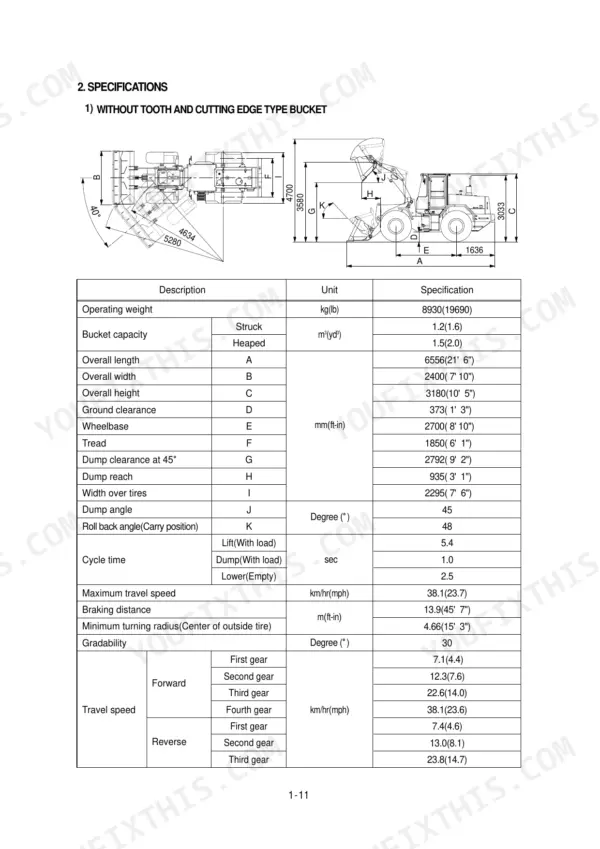
| Specifications | 2-16 | Without Tooth and Cutting Edge Type Bucket, Bolt-On Cutting Edge Type Bucket, With Tooth Type Bucket |
| Engine | 17-20 | Structure, Lube Oil Circuit Schematic, Fuel System Schematic, Cooling System Schematic |
| Power Train System | 21-169 | Power Train Component Overview, Hydraulic Circuit, Torque Converter, Transmission, Axle, Tire and Wheel, Operational Checks and Troubleshooting, Troubleshooting |
| Brake System | 170-208 | Outline, Full Power Hydraulic Brake System, Hydraulic Circuit, Brake Pump, Brake Valve, Brake Accumulator, Pressure Switches, Operational Checks and Troubleshooting |
| Steering System | 209-273 | Outline, Hydraulic Circuit, Priority Valve, Steering Unit, Overload Valve, Steering Cylinder, Operational Checks and Troubleshooting, Troubleshooting |
| Work Equipment | 274-360 | Hydraulic System Outline, Hydraulic Circuit, Work Equipment Hydraulic Circuit, Main Pump Operation, Remote Control Valve, Main Control Valve, Pilot Oil Supply Unit |
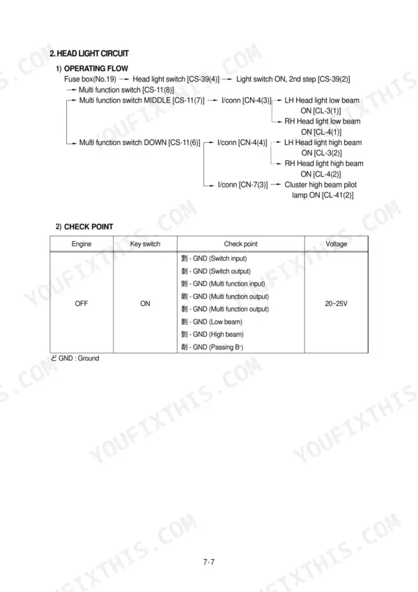
| Electrical System | 361-441 | Component Location, Electrical Circuit, Illumination Circuit, Head Light Circuit, Work Light Switch, Starting Circuit, Fuel Shut Off Circuit, Charging Circuit |
Quick Reference Specifications
| Specification | Value | Page |
|---|---|---|
| Steering unit mounting bolt torque | 2.5 ± 0.5 kgf·m | p. 10 |
| Priority valve mounting bolt torque | 2.5 ± 0.5 kgf·m | p. 10 |
| Main pump housing mounting bolt torque | 19.6 ± 2.9 kgf·m | p. 10 |
| Priority valve relief pressure | 21 MPa | p. 212 |
| Overload valve shock valves pressure | 270-290 bar | p. 220 |
| Hydraulic tank capacity | 60 L (15.9 U.S. gal) | p. 230 |
| Tighten torque for LS plug | 5.1 ± 1 kgf·m (36.9 ± 7.2 lbf·ft) | p. 240 |
| Torque wrench range | 0~7.1 kgf·m (0~51.6 lbf·ft) | p. 243 |
| Tightening torque for Nut (Pipe assy) | 30 ± 3 kgf·m (217 ± 21.7 lbf·ft) | p. 266 |
| Pressure relief valve setting | 3MPa | p. 303 |
| Body bore cut-in depth | 0.15mm | p. 343 |
| Engine Oil Quantity | 12.6 L | p. 7 |