
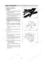
Part of the Hyundai Repair Manuals.
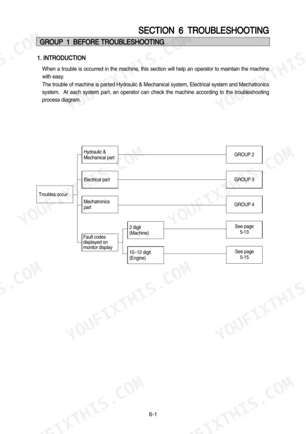
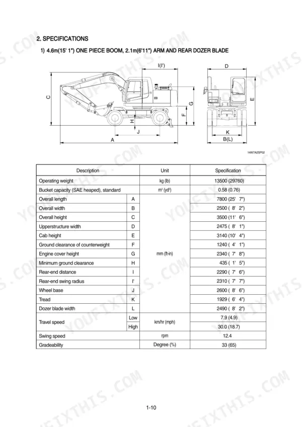
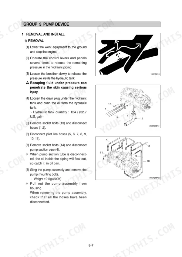
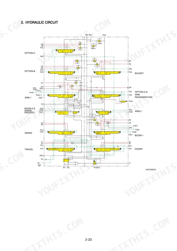
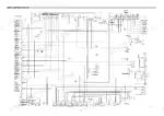
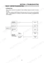
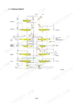
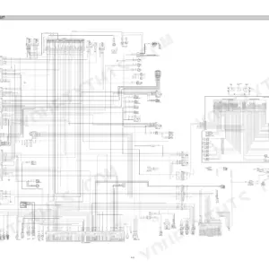
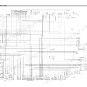
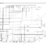
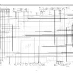
Looking for the Hyundai R140W-7A shop manual PDF? This 620-page factory shop manual walks you through the entire Wheel Excavator: main pump, control valve, swing device, travel motor, transmission, steering, and every work equipment cylinder. You get hydraulic schematics tracing the main and pilot circuits, wiring diagrams with component locations and connector pinouts, and a full troubleshooting section covering hydraulic, electrical, and mechatronics faults, including the self-diagnostic system. Disassembly chapters break each component down step by step, from the pump regulator to the counter-balance valve. Set the bypass check valve at 4.5 kgf/cm2 (64 psi) and keep the overload relief valve under its 390 kgf/cm2 limit. Your machine is parked and the clock is running. Bookmarked chapter by chapter; type a spec, jump to the page, and get back on the sticks.
What's Inside This Hyundai R140W-7A Manual
| System | Pages | Key Topics |
|---|---|---|
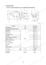
| General | 12-36 | Safety Hints, Specifications |
| Structure and Function | 37-116 | Pump Device, Main Control Valve, Swing Device, Travel Motor, Rcv Lever, Accelerator Pedal, Brake Pedal, Transmission |
| Hydraulic System | 117-149 | Hydraulic Circuit, Main Circuit, Pilot Circuit |
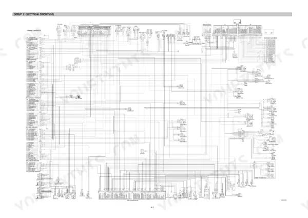
| Electrical System | 150-204 | Component Location, Electrical Circuit, Electrical Component Specification |
| Mechatronics System | 205-238 | Outline, Mode Selection System |
| Maintenance Standard | 289-317 | Operational Performance Test, Major Components, Track and Work Equipment |
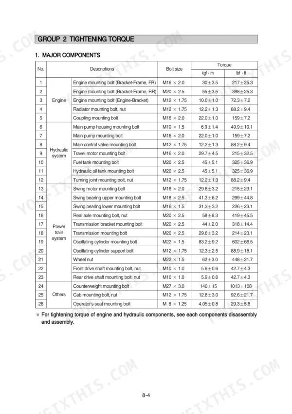
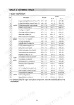
| Precautions and Tightening Torque | 318-324 | Removal Work, Installation Work, Tightening Torque, Pipe and Hose Connections |
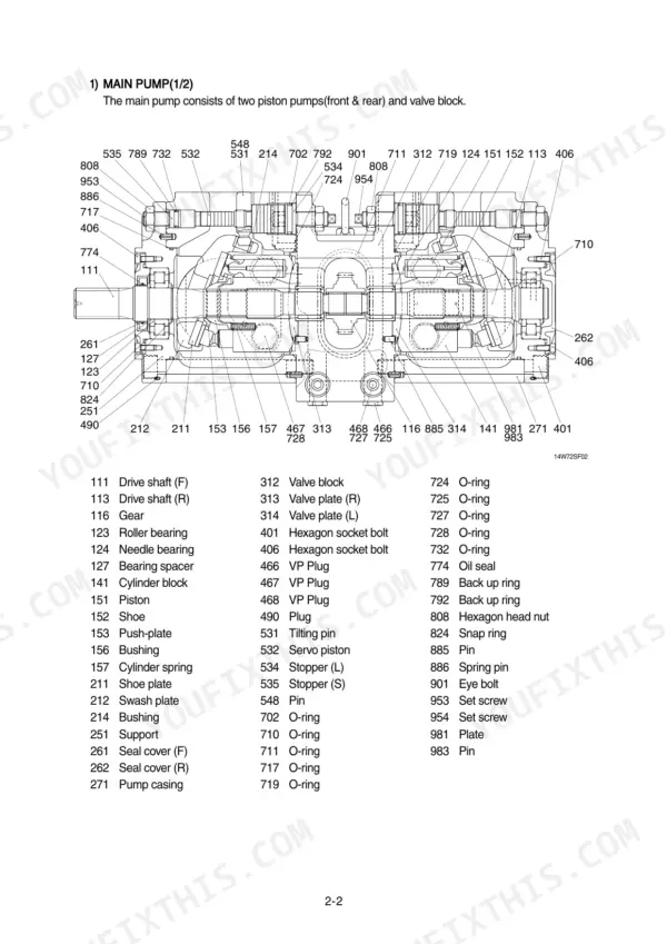
| Pump Device | 325-347 | Main Pump Removal, Main Pump Installation, Regulator Disassembly, Regulator Assembly |
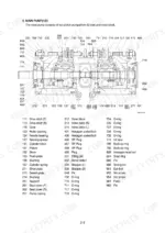
| Main Control Valve | 348-361 | Control Valve Removal, Control Valve Installation, Spool Disassembly, Holding Valve Assembly |
| Swing Device | 362-382 | Swing Motor Removal, Swing Motor Disassembly, Swing Motor Assembly, Reduction Gear Disassembly |
| Travel Motor | 383-406 | Travel Motor Removal, Motor Unit Structure, Control Unit Disassembly, Counter-Balance Valve |
| Transmission | 407-460 | Transmission Removal, Output Disassembly, Brake and Clutch Reassembly, Downshift Interlock |
| Steering Valve and Cylinder | 461-525 | Steering Valve Removal, Steering Valve Disassembly, Steering Cylinder Removal, Steering Cylinder Assembly |
| Work Equipment and Cylinders | 526-604 | Differential Unit Removal, Bevel Pinion Removal, Bucket Cylinder Disassembly, Boom Cylinder Assembly |
| Component Mounting Torque | 605-620 | Introduction Guide, Engine System, Electric System, Power Train System, Structure, Work Equipment |
Quick Reference Specifications
| Specification | Value | Page |
|---|---|---|
| Bypass check valve (1) setting pressure | 4.5kgf/cm2 (64psi) | p. 120 |
| Bypass check valve (2) setting pressure | 3.0kgf/cm2 (43psi) | p. 120 |
| Overload relief valve pressure limit | 390kgf/cm2 | p. 141 |
| Slipper ring clearance | 1.5mm | p. 315 |
| Seal set wear limit | 1.5mm | p. 315 |
| Engine mounting bolt (Bracket-Frame, FR) | 30±3.5 kgf·m | p. 323 |
| Engine mounting bolt (Engine-Bracket) | 10.0±1.0 kgf·m | p. 323 |
| Main relief valve tightening torque | 8~9 kgf·m (57.8~65.1 lbf·ft) | p. 360 |
| Overload relief valve tightening torque | 8~9 kgf·m (57.8~65.1 lbf·ft) | p. 360 |
| Engine oil quantity | 18.5 L | p. 32 |
| Main pump maximum pressure | 330 kgf/cm2 | p. 32 |
| Swing motor relief pressure | 240 kgf/cm2 | p. 33 |
Hyundai R140W-7A Common Problems This Manual Covers
Hyundai R140W-7A swing won't move in either direction, boom and travel still work fine
Check hydraulic oil level first, then tee a gauge into the pilot circuit and verify 40 kgf/cm2 pilot relief pressure per page 122. If pilot checks good, test swing motor relief against the 240 kgf/cm2 spec on page 33. Suspect a stuck swing brake release valve or sticking spool next; spool service starts on page 348.
Manual Section: Hydraulic and Mechanical System TroubleshootingMachine travels straight in one direction only, one side dead or noticeably weaker
Swap the left and right travel relief valves and see if the dead side follows the valve; verify relief pressure against the 360 kgf/cm2 travel spec on page 33. Check travel speed selecting pressure at the J port, 30 to 35 kgf/cm2 in low speed per page 304. Torque any replaced relief valve to 8 to 9 kgf·m.
Manual Section: Hydraulic and Mechanical System TroubleshootingLoud whining or rattling from hydraulic pump, oil looks milky after cold starts
Check hydraulic oil level and viscosity before anything else, then pull and clean the suction strainer and clear the reservoir breather. Inspect the suction line fittings for air ingress. Measure main pump drain pressure; anything over the 1.5 kgf/cm2 (21 psi) limit on page 121 means internal pump wear, not just cavitation.
Manual Section: Hydraulic System p. 121Boom drops slowly under load and moves jerky through the middle of the lift
Test the boom overload relief against the 390 kgf/cm2 limit on page 141, then confirm the system relief holds 330 kgf/cm2. If pressures check out, pull the boom cylinder and measure seal wear; replace the seal kit past the 1.5 mm limit on page 315. Torque the piston lock nut to 100 kgf·m during reassembly.
Manual Section: Work Equipment and Cylinders p. 526Digging power fades once oil warms up, all functions slow at full throttle
Verify main pump delivery pressure at high idle, 330 kgf/cm2 per page 306, before blaming the engine. Low readings point to regulator drift or pump wear; regulator disassembly starts on page 325. If the main relief valve was disturbed during testing, retorque it to 8 to 9 kgf·m per page 360.
Manual Section: Pump Device p. 325Frequently Asked Questions
How do I clear error codes on a Hyundai R140W-7A excavator?
To clear recorded error codes, navigate to the 'Diagnosis' menu on the cluster display, select 'Recorded Error', and then choose 'Yes' when prompted to delete all errors. This process is detailed on page 217 of the manual. p. 217
What do the error codes mean on a Hyundai R140W-7A?
Error codes indicate specific electrical or system malfunctions. For example, code 1 indicates a short circuit in the accel actuator system, while code 34 indicates the controller input voltage is below 18V. A complete list of error codes and their descriptions can be found on pages 218 and 219. p. 218
What are the torque specs for hydraulic fittings on a Hyundai R140W-7A?
Tightening torque for hydraulic fittings depends on the connection type and size. For example, a 1/4" flare type fitting requires 4 kgf·m (28.9 lbf·ft), while a 1/2" flare type fitting requires 9.5 kgf·m (68.7 lbf·ft). Refer to page 324 for a complete table of pipe and hose torque specifications. p. 324
What are the replacement specifications for hydraulic seals?
In principle, all seals, such as O-rings and oil seals, must be replaced with new ones during disassembly and assembly. When fitting O-rings, ensure they are not twisted, as this can cause inadequate sealing and lead to both internal and external oil leakage. p. 360
What is the engine oil capacity for the R140W-7A?
The engine oil capacity for the Mitsubishi D04FD-TAA engine is 18.5 liters (4.9 U.S. gal). p. 32
What exactly do I receive with this Hyundai R140W-7A Shop Manual?
This is a 620-page searchable PDF ready for immediate download. Works on any device, so pull it up on your phone while you're under the hood. No shipping, no waiting.
Does this Hyundai R140W-7A manual allow printing?
Yes. Print the sections you need to take out to the shop for your own use. Standard letter or A4 paper works.






Reviews
There are no reviews yet.