
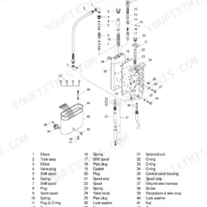
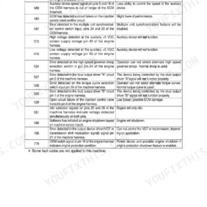
Part of the Hyundai Repair Manuals.
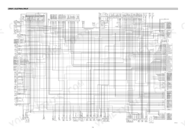
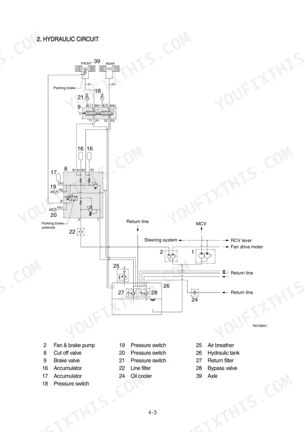
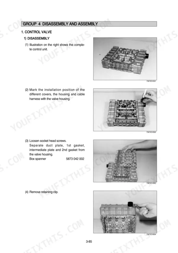
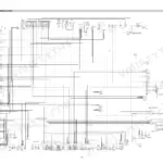
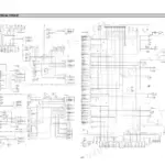
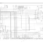
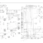
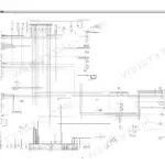
All 589 pages of this Hyundai HL760-7A, HL760XTD-7A service manual PDF cover one machine family: the HL760-7A and HL760XTD-7A wheel loaders, from the powershift transmission down to the Volvo and ZF axles. You get factory wiring diagrams with connector pinouts, full hydraulic schematics, machine and transmission fault code charts for the LCD monitor, and page after page of step-by-step disassembly procedures for the control valve, differential, brakes, steering, and work equipment. Troubleshooting sections walk you from symptom to fix on the power train, brake, and electrical systems. Set the main relief valve at 210 kgf/cm2 (2990 psi), then torque the rubber engine mounting nuts to 57.9 kgf·m. No more chasing wiring faults with a multimeter and a prayer. Bookmarked with a full text layer: search any spec, jump to any section, and get your loader back to work.
What's Inside This Hyundai HL760-7A, HL760XTD-7A Manual
| System | Pages | Key Topics |
|---|---|---|
| General | 1-28 | Safety Hints, Specifications, Operational Checkout Record Sheet |
| Engine | 29-36 | Structure and Function, System Diagrams, Engine Speed and Stall RPM |
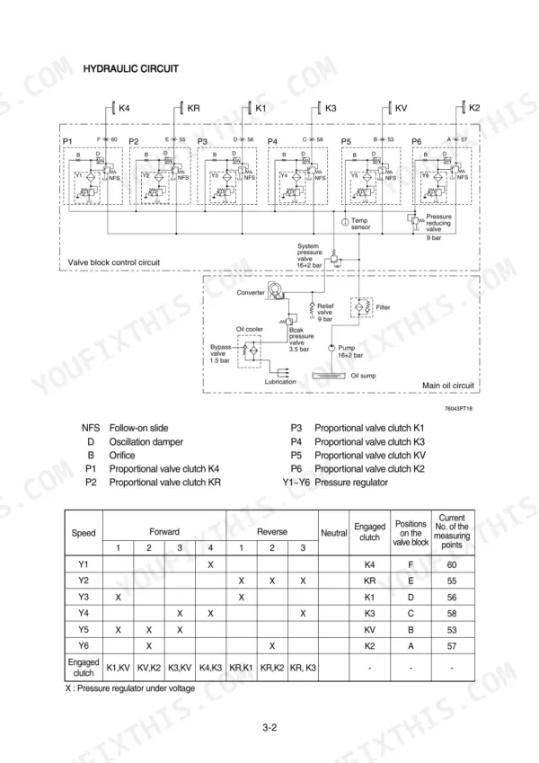
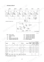
| Power Train Component Overview | 37-41 | Component Overview, Hydraulic Circuit, Torque Converter, Torque Conversion |
| Transmission Layout and Operation | 42-52 | Transmission Layout, Installation View, Operation of Transmission, Electro-Hydraulic Shift Control, Gear Selector |
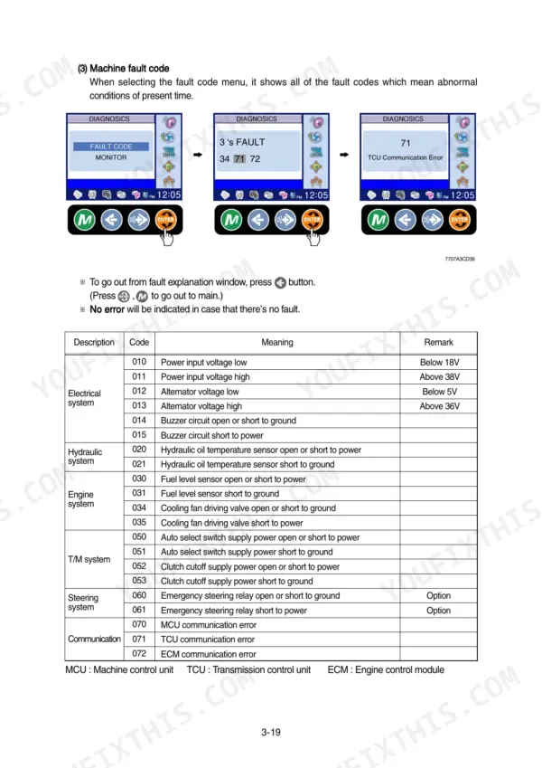
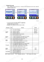
| Monitoring System and Fault Codes | 53-67 | LCD Display, Display Map, Machine Fault Codes, Engine Fault Codes |
| Operating Modes and Transmission Fault Codes | 68-81 | Operating Modes, Transmission Fault Codes, Measuring Resistance, Electrical Control Unit |
| Axle and Differential Systems | 82-108 | Volvo Axle, Zf Axle, Front Axle Differential, Rear Axle Differential, Differential Operation, Torque Proportioning Differential, Final Drive Section, Tire and Wheel |
| Operational Checks and Troubleshooting | 109-122 | Power Train Operational Checks, Transmission Troubleshooting, Measuring Points and Connections, Inductive Transmitter |
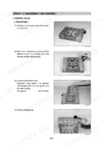
| Disassembly and Assembly | 123-315 | Control Valve Disassembly, Powershift Transmission Disassembly, Differential Assembly, Brake Tubes, Brake System |
| Brake System | 316-363 | Structure and Function, Operational Checks and Troubleshooting, Tests and Adjustments, Disassembly and Assembly |
| Steering System | 364-424 | Structure and Function, Operational Checks and Troubleshooting, Tests and Adjustments, Disassembly and Assembly |
| Work Equipment | 425-506 | Structure and Function, Operational Checks and Troubleshooting, Tests and Adjustments, Disassembly and Assembly |
| Electrical System | 507-589 | Component Location, Electrical Circuit, Monitoring System, Electrical Component Specification, Connectors, Troubleshooting |
Quick Reference Specifications
| Specification | Value | Page |
|---|---|---|
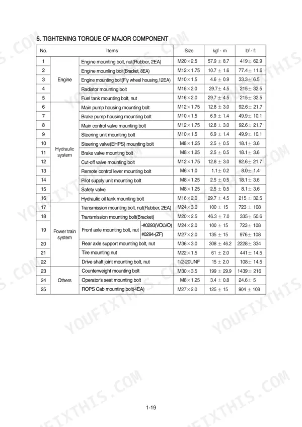
| Engine mounting bolt, nut(Rubber, 2EA) | 57.9 ± 8.7 kgf·m | p. 19 |
| Engine mounling bolt(Bracket, 8EA) | 10.7 ± 1.6 kgf·m | p. 19 |
| Main pump capacity | 68cc/rev | p. 17 |
| Main pump maximum operating pressure | 210kgf/cm² (2990psi) | p. 17 |
| Main relief valve pressure | 210kgf/cm² (2990psi) | p. 17 |
| Overload relief valve pressure(Boom) | 240kgf/cm² (3410psi) | p. 17 |
| Pipe and hose (flare type) 1/2" torque | 9.5 kgf·m | p. 24 |
| Pipe and hose (Orfs type) 13/16-16 torque | 9.5 kgf·m | p. 24 |
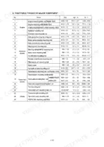
| Relief valve pressure | 9 bar | p. 38 |
| System pressure valve | 16+2 bar | p. 38 |
| Voltage | 20~25V | p. 514 |
| Hydraulic oil temperature warning threshold | 105°C (221°F) | p. 534 |
Hyundai HL760-7A, HL760XTD-7A Common Problems This Manual Covers
Hyundai HL760-7A hydraulic pump grinding, boom slow to lift and bucket weak under load
Test main relief pressure with the bucket cylinder bottomed; spec is 210 kgf/cm2 (2990 psi) on page 20. If pressure is low, do not crank the relief higher to compensate, that ruins a worn pump. Compare pump delivery against the 68 cc/rev rating on page 17 and inspect the suction line for collapse or air leaks.
Manual Section: Work Equipment Troubleshooting p. 425Steering wheel heavy and slow at low idle, gets worse when hydraulic oil is cold
Raise engine speed; if the wheel frees up, the problem is flow, not the column. Remove the steering relief valve, clean the spool and orifice in solvent, and check for score marks or stuck debris, using the steering procedures starting on page 364. On reassembly torque the steering unit mounting bolts to the value in the tightening torque chart (49.9 lbf-ft).
Manual Section: Steering System Troubleshooting p. 364Transmission stuck in gear, dash display ignores selector input, some ranges locked out
Check stored codes through MENU > DIAGNOSTICS > TRANSMISSION > FAULT CODE before pulling parts. Measure solenoid resistance against the tables starting on page 68, and inspect the small selector harness for chafing at the column. Verify transmission oil level against the capacity given in the General specifications. Confirm a job-site speed lockout switch or TCU parameter is not blocking gears.
Manual Section: Operating Modes and Transmission Fault Codes p. 68Warning lamp and buzzer come on during operation with no visible leak or overheating
Pull the stored fault first: MENU > DIAGNOSTICS, then MACHINE, ENGINE, or TRANSMISSION fault code. Match engine codes against the tables starting on page 56. If the hydraulic oil temperature lamp is active, the sender trips at 105 degrees C (221 F) per page 534; clean cooler fins and verify oil level before condemning the sensor.
Manual Section: Monitoring System and Fault Codes p. 56Service brake pedal feels soft and parking brake will not hold machine on a grade
Check accumulator precharge; compare priming pressure against the spec in the brake tests and adjustments on page 333. Bleed the service brakes at each caliper, then measure lining thickness through the inspection port and replace any disc worn past the minimum thickness listed on page 344. Retest holding power on a grade after adjusting the parking brake per the procedures starting on page 316.
Manual Section: Service Brake Troubleshooting p. 333Frequently Asked Questions
What do the error codes mean on a Hyundai HL760-7A?
The error codes for the HL760-7A are listed in the 'Machine fault code' table. For example, code 010 indicates 'Power input voltage low' (below 18V), code 011 indicates 'Power input voltage high' (above 38V), and code 071 indicates a 'TCU communication error'. p. 56
How do I reset the transmission fault code on a Hyundai wheel loader?
Many transmission fault codes, such as 13, 33, 35, 36, 39, and 3C, are reset automatically after power up of the TCU. For other faults, you must perform the specific repair steps listed in the 'Transmission fault codes' table, such as checking cables or connectors. p. 69
What is the hydraulic oil pressure spec for Hyundai HL760-7A service tests?
The main relief valve pressure for the HL760-7A is 210 kgf/cm² (2990 psi). The overload relief valve pressure for the boom is 240 kgf/cm² (3410 psi). p. 20
What is the tightening torque for the transmission mounting bolts on the HL760-7A?
The tightening torque for the transmission mounting bolt and nut (Rubber, 2EA) is 100 ± 15 kgf·m (723 ± 108 lbf·ft). The transmission mounting bolt (Bracket) is 46.3 ± 7.0 kgf·m (335 ± 50.6 lbf·ft). p. 22
What is the engine oil capacity for the HL760-7A?
The engine oil quantity for the Cummins QSB6.7 engine is 18 liters (4.8 U.S. gallons). p. 19
What exactly do I receive with this Hyundai HL760-7A Service Manual?
Instant PDF download. You get the full 589-page searchable Service Manual immediately after payment. Open it on your laptop, tablet, or phone right in the shop.
Is printing allowed for this Hyundai HL760-7A Service Manual?
You can. Print the sections you want for your own use and keep the file as your backup.







Reviews
There are no reviews yet.