
Part of the Hyundai Repair Manuals.
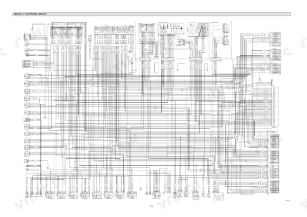
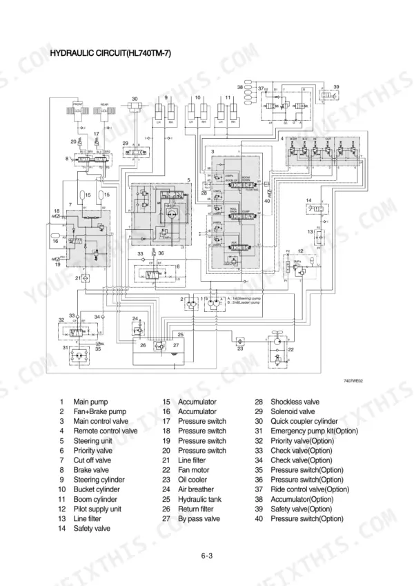
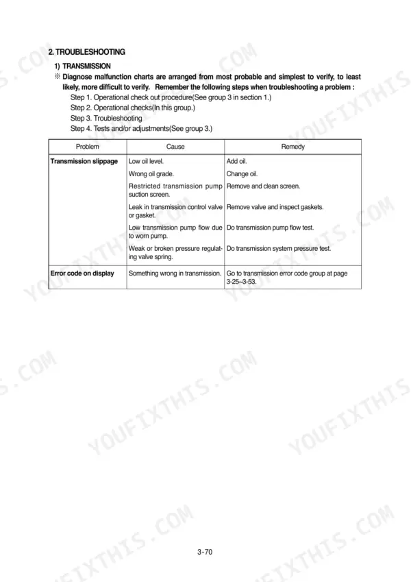
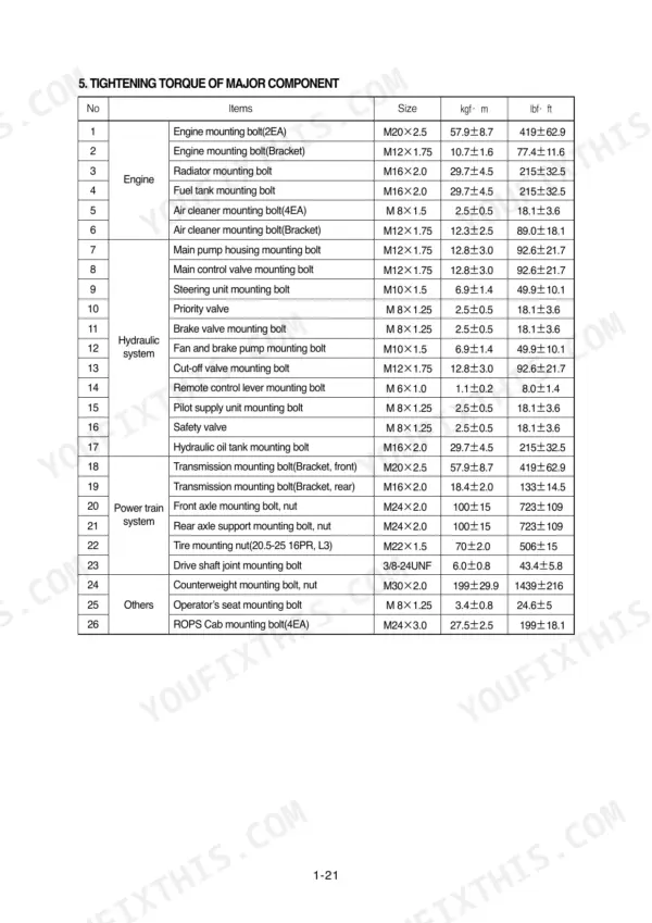
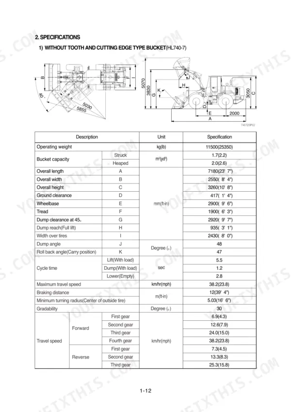
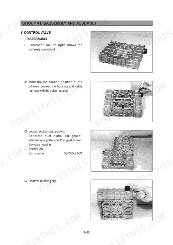
All 500 pages of this Hyundai HL740-7, HL740TM-7 Service Manual PDF focus on one machine: the HL740 series wheel loader, from torque converter to bucket pin. You get factory wiring diagrams for the complete electrical system, hydraulic circuits for the brake, steering, and work equipment systems, plus error code tables and a dedicated power train troubleshooting section. Open the disassembly chapters and follow step-by-step teardowns of the transmission, axles, main pump, and remote control valve. Torque the radiator mounting bolts to 29.7 kgf·m, set the pressure reducing valve at 9 bar, and confirm speed sensor input voltage runs between 0.45 and 7.00 volts. Chasing a transmission fault on forum guesses gets expensive fast. This PDF is bookmarked by system and text-searchable; pull it up on any device in the shop and jump straight to the spec you need.
What's Inside This Hyundai HL740-7, HL740TM-7 Manual
| System | Pages | Key Topics |
|---|---|---|
| General | 11-38 | Safety Hints, Specifications, Operational Checkout Record Sheet |
| Engine | 39-43 | Structure and Function, System Diagrams |
| Power Train System | 44-227 | Power Train Component Overview, Torque Converter, Transmission, Axle |
| Brake System | 228-266 | Structure and Function, Hydraulic Circuit, Brake Pump, Brake Valve |
| Steering System | 267-336 | Structure and Function, Hydraulic Circuit, Steering Unit, Priority Valve, Steering Cylinder |
| Work Equipment | 337-425 | Hydraulic System Outline, Hydraulic Circuit, Main Pump Operation, Remote Control Valve, Main Control Valve |
| Electrical System | 426-500 | Component Location, Electrical Circuit, Monitoring System, Electrical Component Specification, Connectors, Troubleshooting |
Quick Reference Specifications
| Specification | Value | Page |
|---|---|---|
| Radiator mounting bolt | 29.7±4.5 kgf·m | p. 33 |
| Pressure reducing valve | 9 bar | p. 59 |
| System pressure valve | 16+2 bar | p. 59 |
| Engine speed input voltage threshold | 0.45V to 7.00V | p. 74 |
| Turbine speed input voltage threshold | 0.45V to 7.00V | p. 75 |
| Clutch cut-off pressure switch rated pressure | 25kgf/cm2 | p. 121 |
| Minimum thickness of brake discs | 4.5mm | p. 189 |
| Body bore cut-in depth | 0.15mm (0.006") | p. 263 |
| Tightening torque for bolt(23) | 4.8kgf·m (35lbf·ft) | p. 265 |
| Engine Oil Quantity | 16 L | p. 29 |
| Main Relief Valve Pressure | 220 kgf/cm2 | p. 30 |
| Steering Relief Pressure | 20.5-21.5 MPa | p. 292 |
Hyundai HL740-7, HL740TM-7 Common Problems This Manual Covers
Hyundai HL740-7 transmission warning lamp on, shifts erratic or loader will not move in any gear
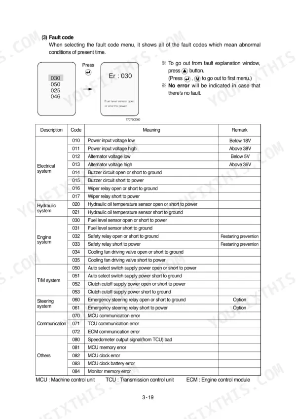
Pull the fault code from the error code reference before touching the gearbox. Check speed sensor connectors first; engine and turbine speed inputs must read between 0.45V and 7.00V per pages 74 and 75. Then work through the transmission troubleshooting procedures, testing TCU wiring and connectors before condemning internal gearbox parts.
Manual Section: Transmission TroubleshootingHydraulic tank level slowly dropping while transmission oil level rises, no external leaks anywhere
Check the transmission dipstick against the hydraulic tank level; a rising transmission with a falling tank means the pump shaft seal is passing oil internally. Replace the seal, inspect the body bore cut-in depth against the 0.15 mm (0.006 inch) limit on page 263, and torque the bolts to 4.8 kgf·m (35 lbf·ft) per page 265.
Manual Section: Work Equipment p. 263Brake fail warning lamp lit, pedal feels weak or brakes barely stop the machine
Park on level ground and shut the machine down; do not keep working with this lamp lit. Check accumulator precharge, which must hold 16 bar, per page 401. Test the charging pressure switch against its 50 to 150 kgf/cm2 range on page 248, then inspect the brake discs and replace any worn below the 4.5 mm minimum thickness.
Manual Section: Service Brake Troubleshooting p. 248Engine or hydraulic oil temperature warning comes on during normal loading and carry work
Clean the radiator and cooler cores with compressed air, check coolant level, and inspect fan belt tension. Verify hydraulic temperature stays below the 80 degree C maximum listed on page 266. If the temperature sensor circuit throws open or short codes, test the wiring before replacing the sensor. When refitting the radiator, torque mounting bolts to 29.7 kgf·m per page 33.
Manual Section: Work Equipment Troubleshooting p. 266Steering wheel heavy and slow at low idle, improves at full throttle
Verify low idle is set to 950 rpm, plus or minus 50, before blaming the pump. Test steering relief pressure against the 20.5 to 21.5 MPa spec on page 292. If pressure only drops at idle, suspect pump wear or a sticking priority valve spool; work through the steering system section starting on page 267.
Manual Section: Steering System Troubleshooting p. 292Frequently Asked Questions
How do I check the monitoring system error codes on a Hyundai HL740TM-7?
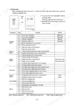
To check error codes, select the fault code menu on the monitor. The display will show all active fault codes indicating abnormal conditions. To exit the fault explanation window, press the back button, or press the menu button to return to the first menu. p. 461
What causes a hydraulic oil temperature warning on the HL740TM-7?
A hydraulic oil temperature warning occurs when the temperature exceeds 105°C (221°F). If this warning lamp flashes and the buzzer sounds, you should check the hydraulic oil level and inspect for debris between the oil cooler and radiator. p. 452
What is the tightening torque for the main pump rear cover bolts?
The tightening torque for the bolts (23) on the main pump rear cover is 4.8 kgf·m (35 lbf·ft). p. 265
What is the recommended oil change interval for the hydraulic oil filter?
The hydraulic oil filter in the filter case of the hydraulic oil tank should be replaced every 250 operating hours. For the first replacement, it should be done at 50 hours. p. 403
What is the correct tightening torque for the boom cylinder nylon nut?
The tightening torque for the nylon nut (18) on the boom cylinder is 250 ± 25 kgf·m (1808 ± 181 lbf·ft). p. 418
What do I get after purchasing this Hyundai HL740-7 manual?
Delivery is instant: a 500-page searchable PDF is yours the second checkout clears. Laptop, tablet, or phone, all fine.
Is printing allowed for this Hyundai HL740-7 Service Manual?
Yes. Print a single page or a chapter for your own shop use, on letter or A4.








Reviews
There are no reviews yet.