

Part of the Hyundai Repair Manuals.
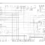
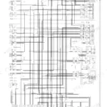
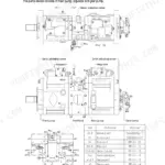
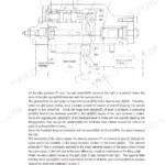
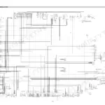
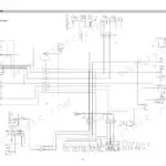
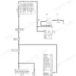
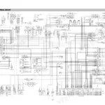
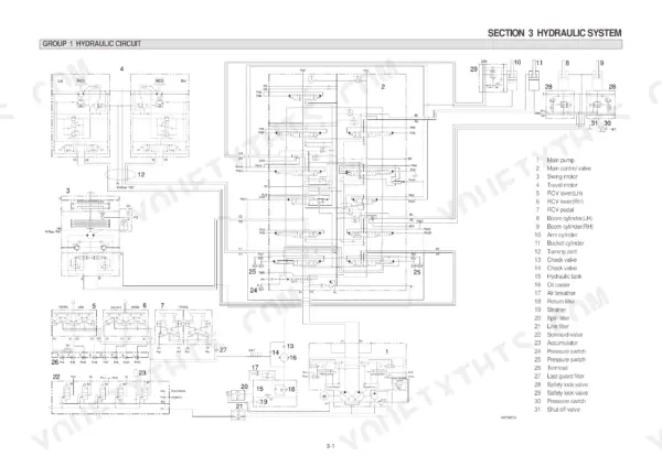
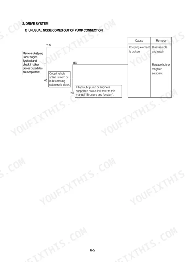
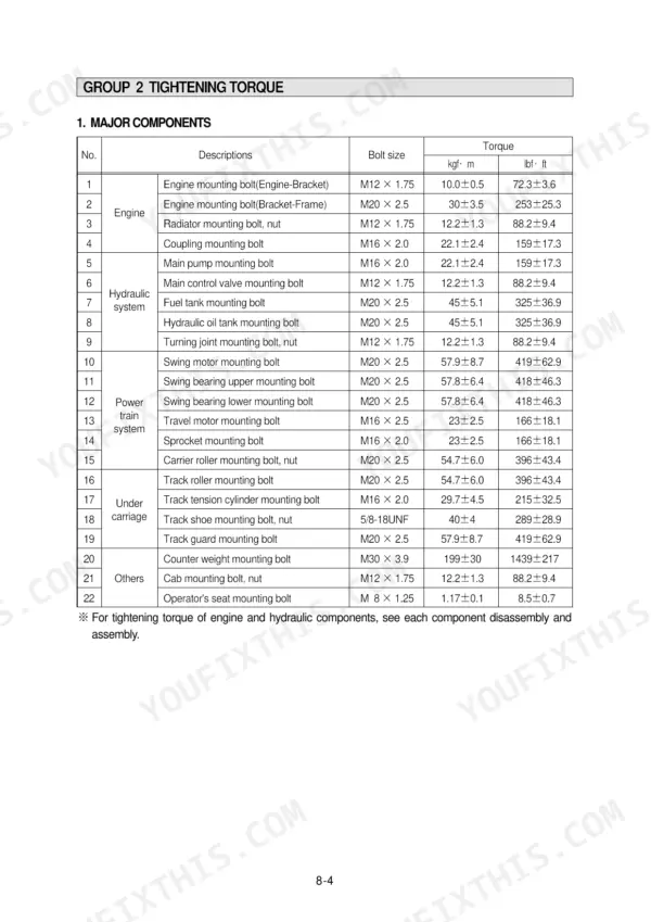
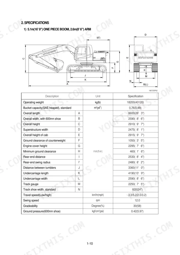
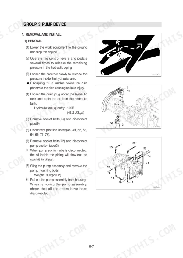
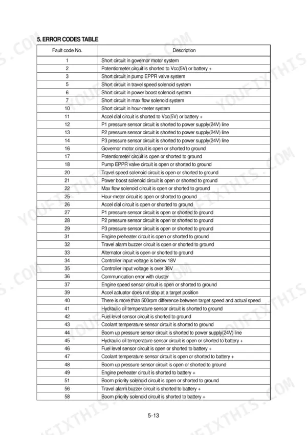
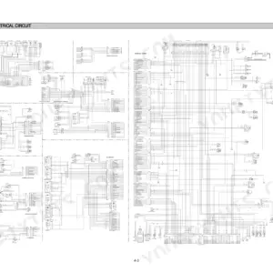
Every one of the 496 pages in this Hyundai R180LC-7 Shop Manual PDF is aimed at one machine: the R180LC-7 crawler excavator, from pump device to undercarriage. Inside: full electrical circuit diagrams with connector pinouts, hydraulic schematics tracing the main and pilot circuits through single and combined operation, and page after page of disassembly and assembly procedures for the pump, main control valve, swing device, and travel motors. You also get component mounting torque tables plus a troubleshooting section that walks the hydraulic, electrical, and mechatronics systems fault by fault. Set the bypass relief valve to open at 1.5 kgf/cm2 (21 psi) and hold axial clearance between the coupling gear and cover to 0.3-0.6 mm during reassembly. Your excavator is dead in the dirt; forum threads won't fix it. Bookmarked, keyword-searchable, and readable on any device you carry into the shop.
What's Inside This Manual
| System | Pages | Key Topics |
|---|---|---|
| General | 11-36 | Safety Hints, Specifications |
| Structure and Function | 37-114 | Pump Device, Main Control Valve, Swing Device, Travel Device, Rcv Lever, Rcv Pedal |
| Hydraulic System | 115-146 | Hydraulic Circuit, Main Circuit, Pilot Circuit, Single Operation, Combined Operation |
| Electrical System | 147-192 | Component Location, Electrical Circuit, Electrical Component Specification, Connectors |
| Mechatronics System | 193-230 | Outline, Mode Selection System |
| Maintenance Standard | 289-323 | Operational Performance Test, Major Components, Track and Work Equipment |
| Disassembly and Assembly | 324-482 | Precaution, Tightening Torque, Pump Device, Main Control Valve, Swing Device, Travel Device, Rcv Lever, Turning Joint |
| Component Mounting Torque | 483-496 | Introduction Guide, Engine System, Electric System, Undercarriage, Structure, Work Equipment |
Quick Reference Specifications
| Specification | Value | Page |
|---|---|---|
| bypass relief valve opening pressure | 1.5kgf/cm2 (21psi) | p. 119 |
| bypass check valve setting pressure | 1.5kgf/cm2 (21psi) | p. 119 |
| Axial clearance between coupling gear(8) and cover(13) | 0.3 to 0.6mm | p. 313 |
| Thrust bearing clearance | 0.8mm | p. 313 |
| Rear flange linear clearance | 10 to 20 μ | p. 314 |
| Maximum allowable rear flange linear clearance | 25 μ | p. 314 |
| Track tension cylinder mounting bolt | 29.7±4.5 kgf·m | p. 329 |
| Track shoe mounting bolt, nut | 40±4 kgf·m | p. 329 |
| Sprocket mounting bolt | 23±2.5 kgf·m | p. 329 |
| Tightening torque for M20x2.5 bolts (Item 5, Group 5) | 54.7±6.0 kgf·m | p. 491 |
| Tightening torque for M16x2.0 bolts (Item 7, Group 4) | 22.0±1.0 kgf·m | p. 489 |
| Tightening torque for M16x2.0 bolts (Item 3, Group 5) | 23±2.5 kgf·m | p. 491 |