

Part of the Hyundai Repair Manuals.
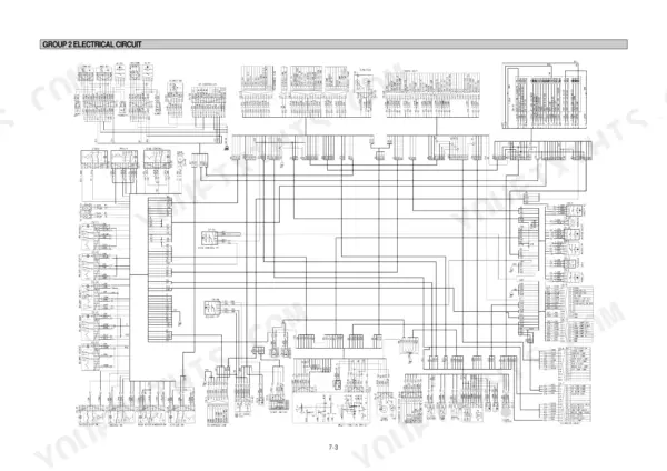
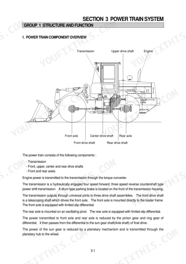
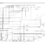
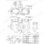
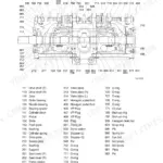
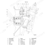
Need the factory answers for your Hyundai HL740-3? This 458-page Hyundai HL740-3 service manual PDF covers the whole wheel loader, from the B5.9-C engine through the full power hydraulic brake system. Inside: complete electrical circuits for the starting, charging, illumination, and engine stop systems, plus hydraulic schematics tracing the torque converter, transmission, priority valve, and remote control valve. A dedicated troubleshooting section is included, and page after page of assembly procedures for the steering unit, brake accumulator, and main pump. Set the shock valves between 270 and 290 bar, and pull the M20 engine mounting bolts to 57.9 ± 8.7 kg·m (419 lb·ft). No more chasing wiring faults with a test light and a hunch. Bookmarked chapters and a real text layer mean you search a spec, find it, and get back on the loader.
Other edition of this manual
What's Inside This Hyundai HL740-3 Manual
| System | Pages | Key Topics |
|---|---|---|
| General | 9-32 | Safety Hints, Specification, Major Component |
| Engine | 33-39 | Structure, Cooling System, Fuel System, Lubricating System, Intake and Exhaust System |
| Power Train System | 40-171 | Power Train Component Overview, Hydraulic Circuit, Torque Converter, Transmission, Egs Lever |
| Brake System | 172-225 | Outline, Full Power Hydraulic Brake System, Hydraulic Circuit, Brake Pump, Brake Valve, Brake Accumulator |
| Steering System | 226-291 | Outline, Hydraulic Circuit, Priority Valve, Steering Unit, Overload Valve, Steering Cylinder |
| Work Equipment | 292-382 | Hydraulic System Outline, Hydraulic Circuit, Rcv Lever Operations, Main Pump Operation, Remote Control Valve |
| Electrical System | 383-458 | Component Location, Electrical Circuit, Illumination Circuit, Head Light Circuit, Work Light Switch, Starting Circuit, Engine Stop Circuit, Charging Circuit |
Quick Reference Specifications
| Specification | Value | Page |
|---|---|---|
| Engine mounting bolt, nut torque | 57.9 ± 8.7 kg·m | p. 26 |
| Radiator mounting bolt, nut torque | 12.3 ± 2.5 kg·m | p. 26 |
| Shock valves | 270-290 bar | p. 237 |
| Hexagon socket screws torque | 6.6 ± 0.5 kgf·m (47.7 ± 3.6 lb·ft) | p. 281 |
| Gland torque | 70 ± 7 kgf·m (506 ± 51 lb·ft) | p. 284 |
| Nylon nut torque | 75 ± 8 kgf·m (542 ± 58 lb·ft) | p. 284 |
| Hydraulic oil filter replacement interval | 250 operating hours | p. 360 |
| Hydraulic oil filter first replacement interval | 50 hours | p. 360 |
| Body bore cut-in limit | 0.15mm | p. 364 |
| Assembly torque wrench range | 0~20kgf·m | p. 362 |
| Working temperature of contact point A/C ON | 4.5°C | p. 421 |
| Working temperature of contact point A/C OFF | 1.5°C | p. 421 |
Hyundai HL740-3 Common Problems This Manual Covers
Hyundai HL740-3 steering wheel heavy at low idle, slow steering response at high idle
Check steering circuit pressure before pulling parts. Main relief pressure is 220 kg/cm2, listed on page 24. If pressure checks good, remove the steering unit and inspect the relief valve and spool for contamination, and verify the shock valve setting of 270-290 bar against page 237. Torque steering unit mounting bolts to 3.3 kg·m on reassembly.
Manual Section: Steering System Troubleshooting p. 226Hydraulic pump whines or growls at operating RPM, bucket and boom functions feel slow
Check hydraulic oil level and viscosity first, then inspect the suction line for kinks and loose clamps pulling air. Remove and clean the suction strainer. Replace the hydraulic oil filter if past its 250 hour interval, noted on page 360. Flow-test the pump; anything well under the 86 L/min maximum on page 349 means the pump is worn.
Manual Section: Hydraulic System Troubleshooting p. 349Engine oil pressure warning lamp comes on while engine is running
Shut the engine off immediately and do not restart until you find the cause. Check oil level and fill to the 16.4 L capacity listed on page 23. If level and pressure both check good but the lamp stays on, trace the sender and lamp circuit using the wiring diagram.
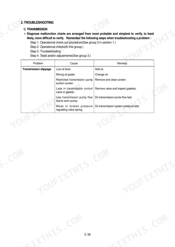
Manual Section: Electrical Troubleshooting: Engine Oil Pressure LampTransmission slips under load or machine will not move in any gear
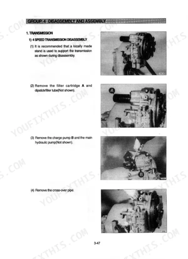
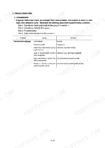
Verify transmission oil level and condition before deeper diagnosis, then work through the troubleshooting procedures starting, which cover slippage, no movement, overheating, and noise. Test drive in each range to isolate the failing clutch pack. If vibration accompanies the complaint, check transmission mounting bolts for the 57.9 ± 8.7 kg·m torque listed on page 26.
Manual Section: Transmission TroubleshootingBoom drops slowly with engine off, bucket curls back with controls in neutral
Measure drift with the bucket loaded and controls in neutral. Boom cylinder drift limit is 40 mm and bucket cylinder limit is 20 mm, both listed on page 353. Past those limits, inspect cylinder piston seals for bypass and check the main control valve; port relief valves should hold 240 bar per page 311.
Manual Section: Hydraulic System Troubleshooting p. 353Frequently Asked Questions
What are the replacement specifications for the hydraulic pump?
The main hydraulic pump has a maximum delivery pressure of 220 kg/cm² (3129 psi) for models #0053 and up, with a rated oil quantity of 163 l/min (43 U.S. gpm) at 2200 rpm. For models up to #0052, the rated oil quantity is 277 l/min (20.3 U.S. gpm) at 2200 rpm. p. 23
What is the procedure for the hydraulic oil warm-up?
To warm up the hydraulic oil, hold a hydraulic function over relief for no more than 5 seconds at a time. Periodically cycle all hydraulic functions to distribute the warm oil until the hydraulic tank is uncomfortable to touch, which corresponds to approximately 45-55°C. p. 334
What is the torque specification for the main control valve tie rod nuts?
When assembling the main control valve, the two 11/16 nuts should be torqued to 48 ± 5 lbf·ft, and the 3/4 nut should be torqued to 74 ± 8 lbf·ft. p. 372
What is the required clearance for the boom height kickout proximity switch?
The clearance between the plate(B) and the probe of the proximity switch must be adjusted to 3 ± 1mm. p. 346
What is the maximum allowable leakage for the boom and bucket cylinders?
The maximum leakage for the boom and bucket cylinders is 12cc/10min when tested at low idle with the oil at 40 ± 6°C. p. 354
What format is this Hyundai HL740-3 manual in?
You download the Service Manual yourself: 458 pages, searchable PDF, available immediately. Keep a copy on every device you use.
Can I print just the pages I need from this Hyundai HL740-3 manual?
Yes. Many mechanics print the section they need for their own shop and bring it to the bench.







Reviews
There are no reviews yet.