
Part of the Hyundai Repair Manuals.
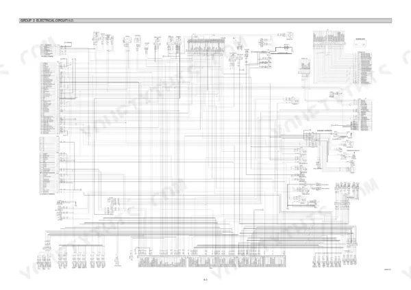
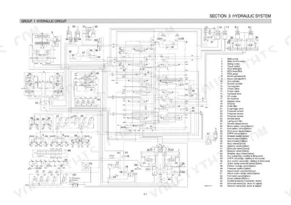
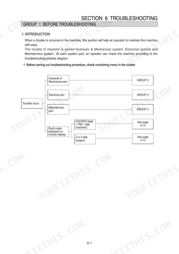
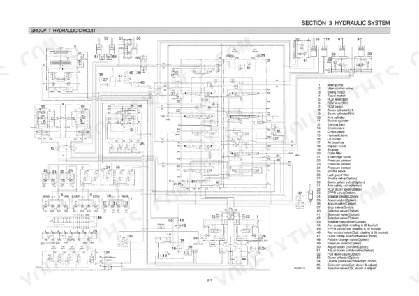
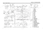
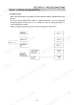
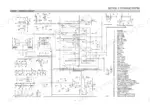
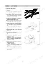
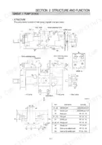
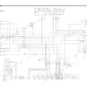
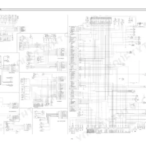
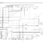
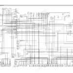
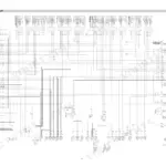
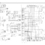
All 544 pages of this Hyundai R160–R180 series shop manual PDF cover one machine family: the R160LC-9, R160LCD-9, R180LC-9, R180LCD-9, and R180NLC-9 hydraulic excavators. You get full hydraulic schematics tracing the main and pilot circuits through single and combined operation, electrical wiring diagrams with component locations and connector pinouts, and a complete mechatronics section covering mode selection, auto-deceleration, and power boost. Open to the troubleshooting charts when your self-diagnostic system throws a code, or hit the disassembly section for pump, main control valve, swing, and travel device rebuilds. Set boom, arm, and bucket relief pressure to 350 ± 10 kgf/cm2 and fill the hydraulic tank to 124 L before you test. No more chasing wiring faults with a multimeter and a prayer. Bookmarked with a full text layer: search any spec, jump to any section, fix the machine.
What's Inside This Hyundai R160LC-9 / R180LC-9 Manual
| System | Pages | Key Topics |
|---|---|---|
| General | 1-47 | Safety Hints, Specifications |
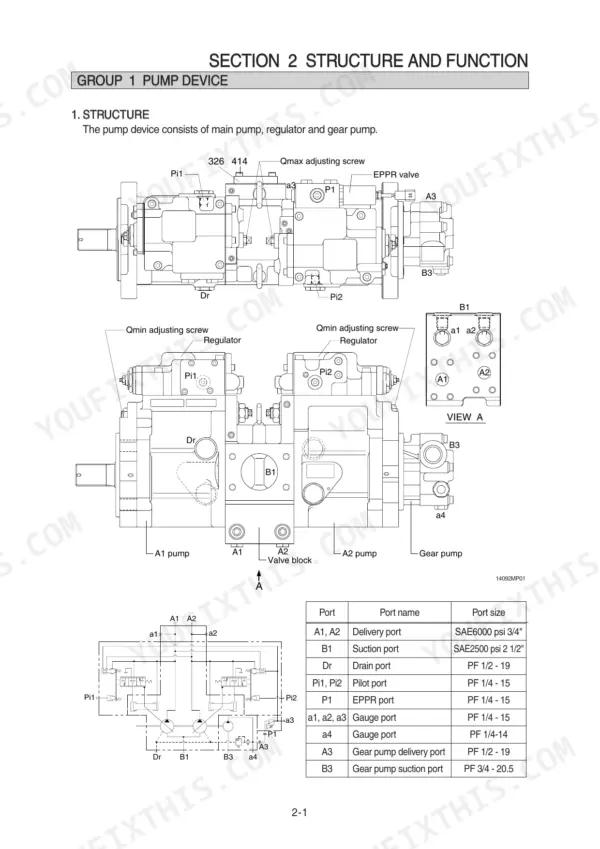
| Structure and Function | 48-125 | Pump Device, Main Control Valve, Swing Device, Travel Device, Rcv Lever, Rcv Pedal |
| Hydraulic System | 126-158 | Hydraulic Circuit, Main Circuit, Pilot Circuit, Single Operation, Combined Operation |
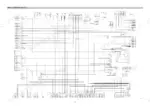
| Electrical System | 159-210 | Component Location, Electrical Circuit, Electrical Component Specification, Connectors |
| Mechatronics System | 211-260 | Mode Selection System, Automatic Deceleration System, Power Boost System, Travel Speed Control System, Engine Overheat Prevention System, Self-Diagnostic System |
| Maintenance Standard | 331-365 | Operational Performance Test, Major Components, Track and Work Equipment |
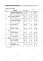
| Disassembly and Assembly | 366-518 | Precaution, Tightening Torque, Pump Device, Main Control Valve, Swing Device, Travel Device, Rcv Lever, Turning Joint |
| Component Mounting Torque | 519-544 | Engine System, Electric System, Hydraulic System, Undercarriage, Structure, Work Equipment |
Quick Reference Specifications
| Specification | Value | Page |
|---|---|---|
| All Models | ||
| Bypass relief valve (full-flow filter) | 1.5 kgf/cm2 | p. 129 |
| Relief valve (pilot circuit) | 40 kgf/cm2 | p. 131 |
| Drain oil pressure limit | 1.5 kgf/cm2 | p. 130 |
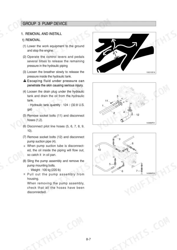
| Hydraulic tank quantity | 124 L (32.8 U.S. gal) | p. 373 |
| Engine oil quantity | 17.5 L | p. 26 |
| Main relief valve pressure | 350 kgf/cm2 | p. 15 |
| Swing motor relief pressure | 285 kgf/cm2 | p. 15 |
| Travel motor relief pressure | 350 kgf/cm2 | p. 15 |
| Engine oil pan capacity | 17.5 L | p. 29 |
| Fuel tank capacity | 260 L | p. 29 |
| R160LC-9 | ||
| Operating weight (R160LC-9) | 17800 kg | p. 12 |
| R180LC-9 | ||
| Operating weight (R180LC-9) | 18600 kg | p. 31 |
Hyundai R160LC-9 / R180LC-9 Common Problems This Manual Covers
Hyundai R160LC-9 boom drops and bucket opens by itself with pilot valve in neutral
Test the overload relief valves first. Cylinder drift in neutral usually means a relief valve port is bleeding oil below its set pressure. Verify boom, arm, and bucket relief pressure against the 350 (380) ± 10 kgf/cm2 standard on page 351. If a valve reseats low, replace it and torque to 8~9 kgf·m (57.8~65.1 lbf·ft).
Manual Section: Attachment System Troubleshooting p. 351All functions weak in both directions, boom and arm barely lift under load
Check main relief pressure at the pump test port; it should hold 350 kgf/cm2 per the spec on page 15. If pressure reads low across every circuit, drain the tank and pull the return filter. Seal fragments from a damaged element block flow, and the bypass relief opens at just 1.5 kgf/cm2, so debris passes straight through unfiltered.
Manual Section: Hydraulic and Mechanical System Troubleshooting p. 15Hydraulic oil leaks from pump housing after suction pipe removal and reinstall
Pull the pump back off and inspect every O-ring on the suction flange and regulator mount; they tear or drop out during removal without anyone noticing. Replace them all, never reuse. Follow the service procedure starting on page 373, then refill the tank to the 124 L (32.8 U.S. gal) level and bleed air from the pump before starting.
Manual Section: Disassembly and Assembly p. 373Swing drifts after stopping on a slope and upper structure creeps in neutral
Test the swing motor relief valves; the maintenance standard on page 351 is 275 ± 10 kgf/cm2. If pressure holds, check the swing parking brake for slow engagement, then inspect the motor case drain since heavy drain flow means a worn rotary group. Compare drain pressure against the 1.5 kgf/cm2 limit on page 130.
Manual Section: Swing Device Troubleshooting p. 351Pilot controls feel dead, no lever response even though the engine runs fine
Check pilot pressure at the remote control valve supply line; the pilot circuit relief is set at 40 kgf/cm2, spec on page 131. Zero pressure points to a stuck pilot relief, blocked line filter, or the safety solenoid valve not energizing, so verify the safety lever switch and solenoid before pulling the pilot pump.
Manual Section: Hydraulic and Mechanical System Troubleshooting p. 131Frequently Asked Questions
What are the torque specifications for the main pump housing mounting bolts on the Hyundai R160LC-9?
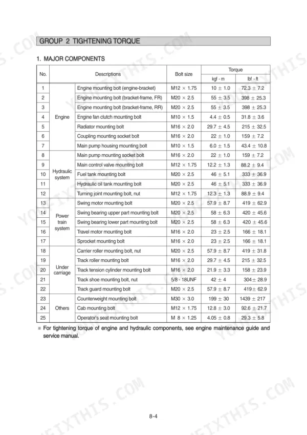
The main pump housing mounting bolts (M10 x 1.5) on the Hyundai R160LC-9 should be tightened to a torque of 6.0 ± 1.5 kgf·m (43.4 ± 10.8 lbf·ft). p. 370
What are the replacement specifications for the hydraulic oil return filter?
The hydraulic oil return filter should be replaced every 1000 hours of operation. p. 253
What is the procedure for bleeding air from the hydraulic pump after installation?
After installing the pump, remove the air vent plug (2EA), tighten it lightly, start the engine at low idling until oil comes out, and then tighten the plug fully. Finally, run the engine at low idling for 3 to 5 minutes to circulate the oil. p. 374
What is the standard clearance for the swing bearing play?
The standard clearance for the swing bearing play is 0.5 to 1.5 mm, with a maximum allowable limit of 3.0 mm. p. 341
What is the tightening torque for the bucket cylinder gland mounting socket head bolts?
The gland mounting socket head bolts for the bucket cylinder (M14 x 2.0) should be tightened to 15 ± 2.0 kgf·m (108 ± 14.5 lbf·ft). p. 495
Is this Hyundai R160–R180 Series Shop Manual a digital download?
Immediate download of the complete 544-page searchable Shop Manual. Access it on any device, from a laptop at your desk to a phone in the field.
Is this Hyundai R160–R180 Series Shop Manual printable?
Yes. Print individual pages or full chapters for your own shop use, on letter or A4 paper.







Reviews
There are no reviews yet.