


Part of the Hyundai Repair Manuals.
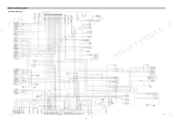
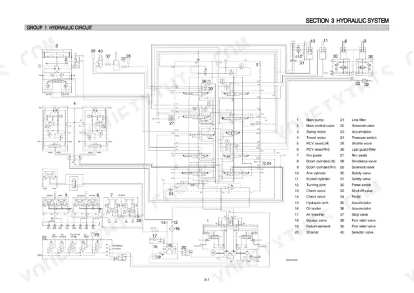
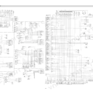
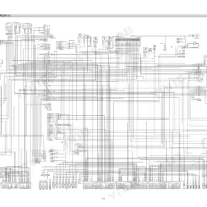
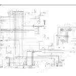
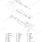
Need the factory shop manual PDF for your Hyundai R290LC-7A or R290NLC-7A crawler excavator? All 510 pages cover the standard machines plus the Long Reach and High Walker variants. Inside: full hydraulic circuit schematics tracing main and pilot lines, complete electrical wiring diagrams with connector pinouts, and a self-diagnostic section that decodes every fault the mechatronics system throws. You also get step-by-step disassembly and assembly for the pump device, main control valve, swing and travel drives, backed by page after page of component mounting torque tables. Check the bypass relief valve at 1.5 kgf/cm2 (21 psi) and confirm the hydraulic oil temperature sensor reads 130 to 150 ohms before you condemn a harness. No more chasing wiring faults with a multimeter and a prayer. Bookmarked with a full text layer; search any spec, jump to any section, get back to digging.
What's Inside This Hyundai R290LC-7A, R290NLC-7A Manual
| System | Pages | Key Topics |
|---|---|---|
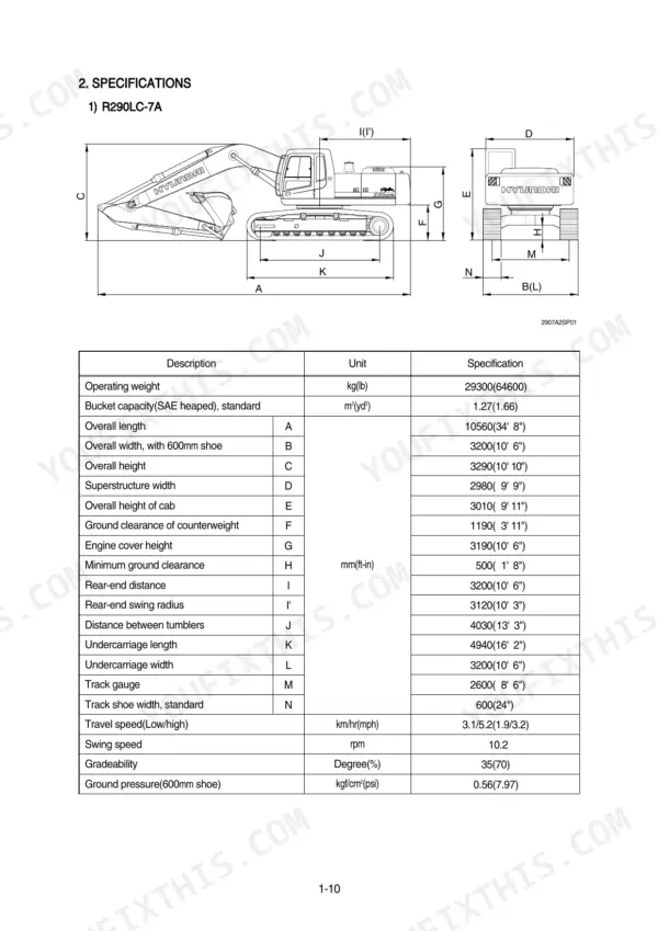
| General | 11-48 | Safety Hints, Specifications |
| Structure and Function | 49-125 | Pump Device, Main Control Valve, Swing Device, Travel Device, Rcv Lever, Rcv Pedal |
| Hydraulic System | 126-157 | Hydraulic Circuit, Main Circuit, Pilot Circuit |
| Electrical System | 158-203 | Component Location, Electrical Circuit, Electrical Component Specification |
| Mechatronics System | 204-258 | Outline, Mode Selection System, Automatic Deceleration System |
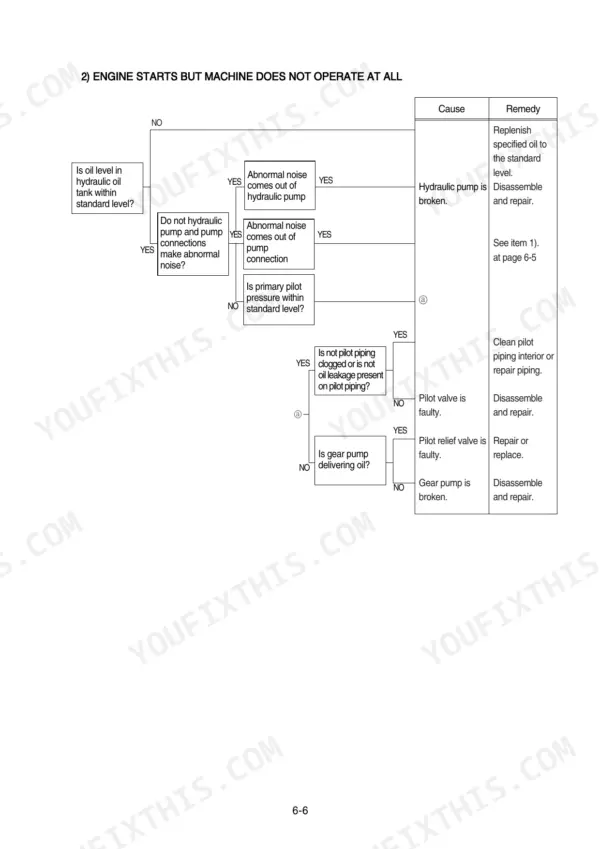
| Troubleshooting | 259-308 | Before Troubleshooting, Hydraulic and Mechanical System, Electrical System, Mechatronics System |
| Maintenance Standard | 309-343 | Operational Performance Test, Major Components, Track and Work Equipment |
| Disassembly and Assembly | 344-494 | Precaution, Tightening Torque, Pump Device, Main Control Valve, Swing Device, Travel Device, Rcv Lever, Turning Joint |
| Component Mounting Torque | 495-510 | Introduction Guide, Engine System, Electric System, Undercarriage, Structure, Work Equipment |
Quick Reference Specifications
| Specification | Value | Page |
|---|---|---|
| All Models | ||
| Bypass relief valve opening differential pressure | 1.5kgf/cm2 (21psi) | p. 129 |
| Drain oil pressure limit | 1.5kgf/cm2 (21psi) | p. 130 |
| Hydraulic oil temperature sensor resistance | 130-150 Ω | p. 289 |
| Main relief valve, port relief valve & negative control relief valve - O-rings, back up rings and seals | 100% replacement | p. 331 |
| Balance plate - Worn less than | 0.03mm | p. 331 |
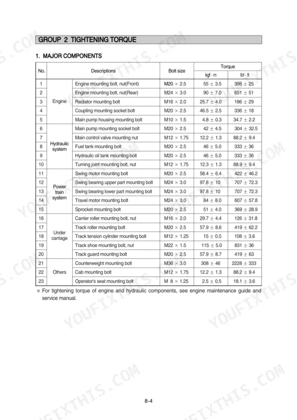
| Swing motor mounting bolt torque | 58.4 ± 6.4 kgf·m | p. 344 |
| Swing bearing upper part mounting bolt torque | 97.8 ± 10 kgf·m | p. 344 |
| Overload relief valve tightening torque | 8~9 kgf·m (57.8~65.1 lbf·ft) | p. 383 |
| Socket head bolt (Bucket cylinder, Item 22, M18) torque | 32.0±3.0 kgf·m (232±21.7 lbf·ft) | p. 471 |
| Socket head bolt (Bucket cylinder, Item 31, M12) torque | 9.4±1.0 kgf·m (68.0±7.2 lbf·ft) | p. 471 |
| R290LC-7A | ||
| Operating Weight, R290LC-7A | 29300 kg | p. 21 |
| R290NLC-7A | ||
| Operating Weight, R290NLC-7A | 29100 kg | p. 22 |
Hyundai R290LC-7A, R290NLC-7A Common Problems This Manual Covers
Hyundai R290LC-7A boom, arm, and bucket power weak, all hydraulic functions slow under load
Check the main relief valve first when every circuit is weak. Follow the boom, arm and bucket power troubleshooting flow starting. If the valve needs work, replace all O-rings, back-up rings and seals (100 percent replacement per page 331) and torque the cartridge to 8~9 kgf·m (57.8~65.1 lbf·ft) per page 383.
Manual Section: Hydraulic and Mechanical System TroubleshootingBoom or arm drifts down slowly with all control levers locked in neutral position
Test the oil port relief valves before pulling a cylinder; a valve opening below spec mimics cylinder leakage. Swap suspect relief valves between circuits and see if the drift follows. If a cylinder is leaking internally, reseal it and torque the piston to 100±10.0 kgf·m (723±72.3 lbf·ft) per page 471.
Manual Section: Hydraulic and Mechanical System TroubleshootingFault code 37 on cluster, engine speed sensor circuit open, auto decel not working
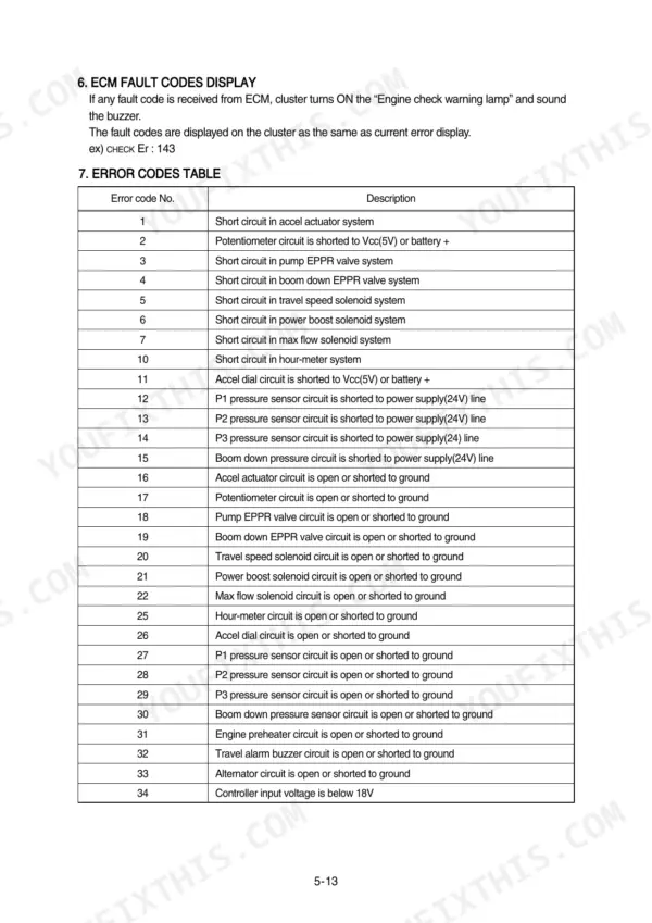
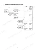
Check the engine speed sensor connector and harness for opens or shorts to ground using the error code reference and the wiring diagram on page 161. Code 40 sets when actual engine speed differs from target by more than 500 rpm, so confirm the auto-decel drop to 1050 rpm after four seconds with every lever in neutral before you call the repair good.
Manual Section: Mechatronics System Troubleshooting p. 161Hydraulic functions erratic once oil warms up, temperature sensor code 41 flashing on cluster
Unplug the hydraulic oil temperature sensor connector CD-1 and measure resistance across pins 1 and 2; the reading should fall between 130 and 150 Ω per the procedure on page 289. Replace the sensor if out of range, otherwise trace the harness for a short to ground before condemning the controller.
Manual Section: Electrical System Troubleshooting p. 289Hydraulic pump noisy and oil looks cloudy in tank sight glass after filter service
Drain and inspect the return filter element for collapse and debris. Verify the bypass relief valve opens at 1.5 kgf/cm2 (21 psi) as listed on page 129, then bleed air at the pump and check suction line clamps for leaks. Follow the cavitation and cloudy oil troubleshooting steps starting.
Manual Section: Hydraulic System p. 129Frequently Asked Questions
How do I clear fault codes on a Hyundai R290LC-7A excavator?
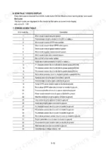
To delete all recorded error codes, select the recorded error (TIME Er) display on the cluster. Press the engine and select switch at the same time for 2 seconds or more. The cluster display will change to 'TIME Er : 00', indicating that the CPU controller has deleted all recorded error codes from the memory. p. 216
What is the torque specification for the R290LC-7A track roller mounting bolts?
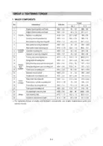
The torque specification for the track roller mounting bolts (M20 x 2.5) is 57.9 ± 8.6 kgf·m (419 ± 62.2 lbf·ft). p. 348
What are the replacement specifications for the Main relief valve?
The main relief valve should be replaced if there is external rusting or damage, if the contacting face of the valve seat or poppet is damaged, or if the spring is abnormal. It is recommended to perform a 100% replacement of O-rings, back-up rings, and seals during maintenance. p. 331
What is the tightening torque for the engine mounting bolts (front) on the R290LC-7A?
The tightening torque for the front engine mounting bolts (M20 x 2.5) is 55 ± 3.5 kgf·m (398 ± 25 lbf·ft). p. 348
What is the hydraulic tank capacity for the R290LC-7A?
The hydraulic tank capacity is 210 liters (55.5 U.S. gal). p. 351
Is this Hyundai R290LC-7A manual a PDF I download?
Instant PDF download. You get the full 510-page searchable Shop Manual immediately after payment. Open it on your laptop, tablet, or phone right in the shop.
Can I print just the pages I need from this Hyundai R290LC-7A manual?
Yes. Many buyers print one chapter at a time for their own shop and keep the rest on a tablet.








Reviews
There are no reviews yet.