

Part of the Hyundai Repair Manuals.
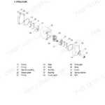
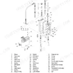
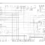
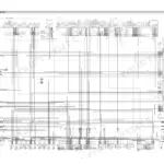
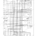
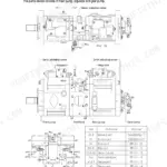
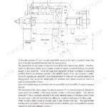
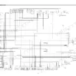
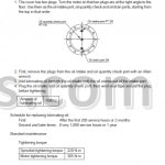
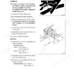
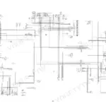
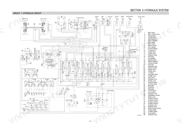
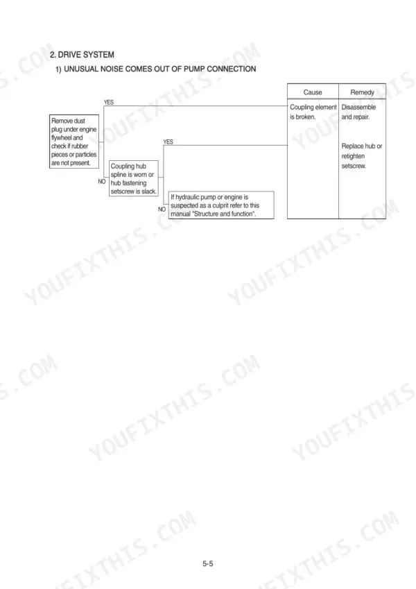
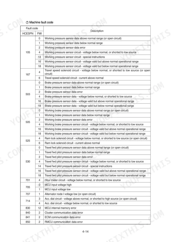
All 487 pages of this Hyundai R55W-9 shop manual PDF focus on one machine: the R55W-9 wheel excavator, from pump device to axle. Inside you get full hydraulic circuit diagrams covering the main and pilot circuits plus single and combined operations, a complete electrical section with circuit drawings, connector layouts, and monitoring system coverage, and page after page of disassembly and assembly procedures for the pump, main control valve, swing and travel devices, gear box, and steering valve. Troubleshooting charts walk you through hydraulic, electrical, and axle faults step by step. Set the T1 hydraulic fitting to 10~12 kgf·m, the port fittings to 6.0~7.0 kgf·m, and swap filters every 500 hours. Chasing a wiring fault without a diagram is a losing game. Bookmarked with a live text layer; jump to any section or search any spec, right from the shop floor.
What's Inside This Manual
| System | Pages | Key Topics |
|---|---|---|
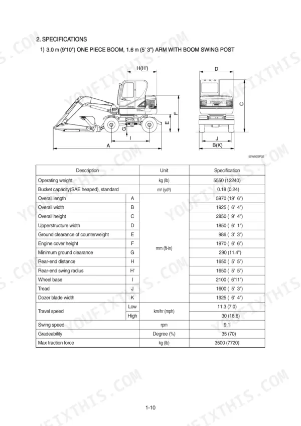
| General | 3-21 | Safety Hints, Specifications |
| Structure and Function | 22-88 | Pump Device, Main Control Valve, Swing Device, Travel Device, Rcv Lever, Rcv Pedal, Brake Pedal, Gear Box |
| Hydraulic System | 89-118 | Hydraulic Circuit, Main Circuit, Pilot Circuit |
| Electrical System | 119-179 | Component Location, Monitoring System, Electrical Circuit |
| Troubleshooting | 180-202 | Before Troubleshooting, Hydraulic and Mechanical System, Axle |
| Maintenance Standard | 203-232 | Operational Performance Test, Major Components |
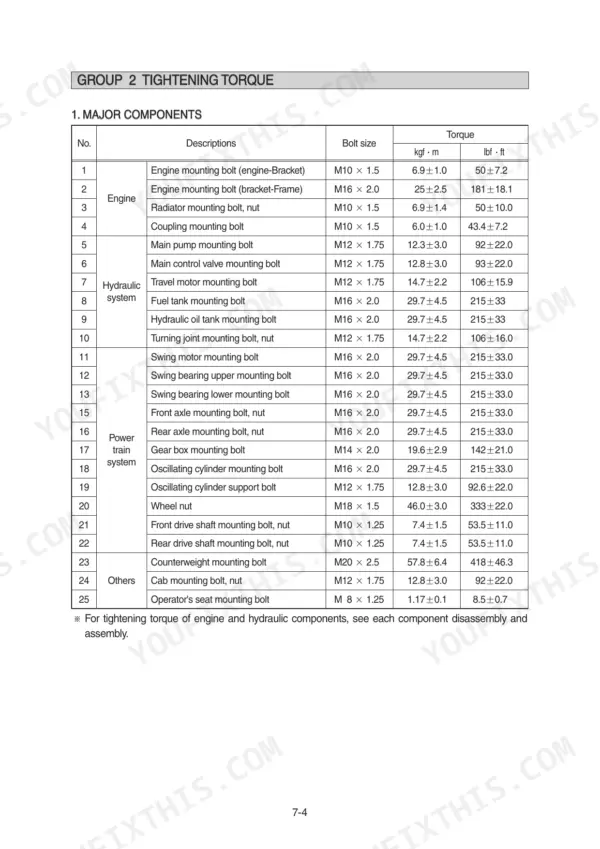
| General Precautions and Tightening Torque | 233-240 | Removal Work, Install Work, Completing Work, Tightening Torque Chart |
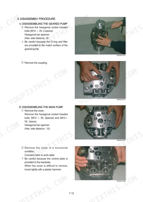
| Pump Device | 241-270 | Removal and Install, Structure, Disassembly, Assembly, Tools and Tightening Torque |
| Main Control Valve | 271-285 | Removal and Install, Structure, Disassembly, Inspection, Assembly |
| Swing Device | 286-306 | Removal and Install, Structure, Disassembly, Assembly, Swing Reduction Gear |
| Travel Motor | 307-330 | Removal and Install, Motor Unit Structure, Control Unit, Counter-Balance Valve, Sealing |
| Gear Box | 331-357 | Removal and Install, Structure, Disassembly, Assembly, Gearshift Cylinder |
| Steering Valve | 359-379 | Removal and Install, Structure, Disassembly, Assembly, Dual Shock Valve |
| Axle and Work Equipment | 380-467 | Axle Removal, Differential Disassembly, Steering Cylinder, Bucket Assembly, Arm Assembly, Boom Cylinder |
| Component Mounting Torque | 468-487 | Introduction Guide, Engine System, Electric System, Power Train, Structure, Work Equipment |
Quick Reference Specifications
| Specification | Value | Page |
|---|---|---|
| Battery | 1 x 12V x 100Ah | p. 17 |
| P1, P2, P3, A1, B1, A2, B2, A4, B4, A5, B5, A6, B6, A7, B7, A8, B8, A9, B9, A10, B10, B11, T2 tightening torque | 6.0~7.0 kgf·m | p. 31 |
| T1 tightening torque | 10~12 kgf·m | p. 31 |
| Filter change interval | 500 hours | p. 29 |
| Bypass relief valve opening pressure | 1.5 kgf/cm2 | p. 92 |
| Fuse 1 | 30A | p. 137 |
| Fuse 2 | 20A | p. 137 |
| Engine mounting bolt (engine-Bracket) | 6.9±1.0 kgf·m | p. 237 |
| Engine mounting bolt (bracket-Frame) | 25±2.5 kgf·m | p. 237 |
| Operating weight | 5550 kg | p. 13 |
| Travel speed (High) | 30 km/hr | p. 13 |
| Engine oil quantity | 11.6 L | p. 18 |