


Part of the Hyundai Repair Manuals.
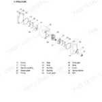
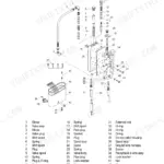
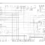
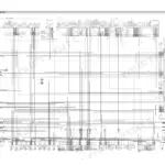
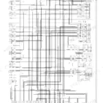
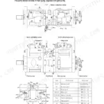
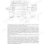
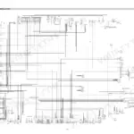
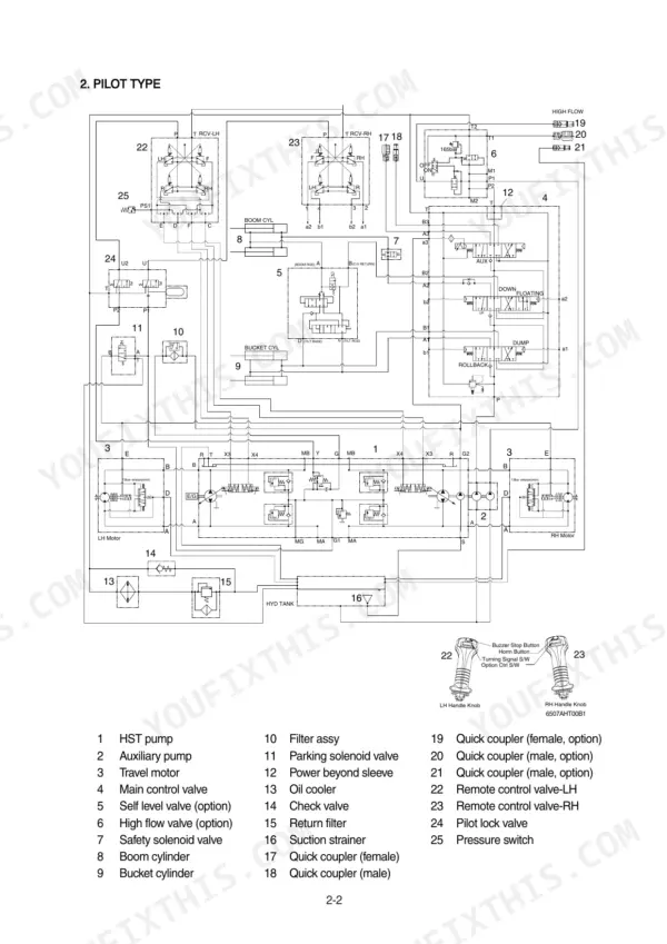
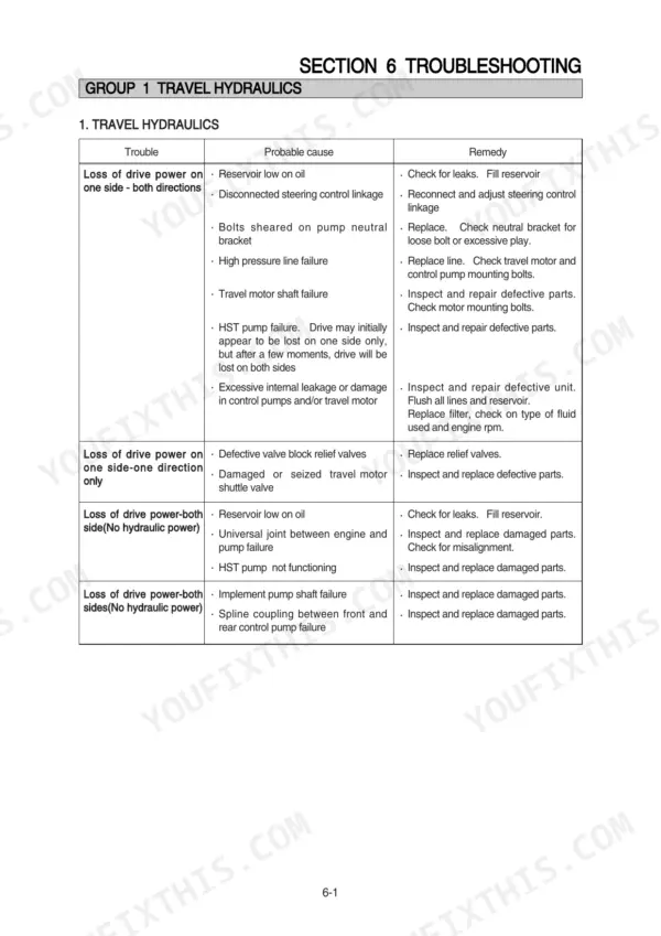
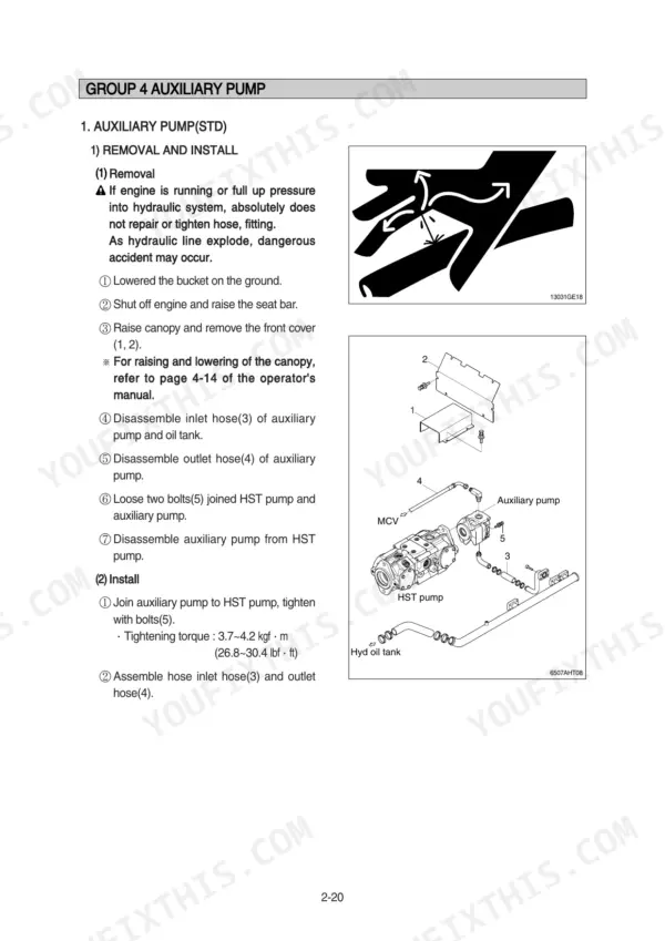
Need factory answers for your Hyundai HSL650-7A skid steer loader? This 194-page Hyundai HSL650-7A service manual PDF walks you through the HST pump, travel motors, main control valve, and every hydraulic circuit in between. Inside: full wiring diagrams with electrical component locations, hydraulic schematics for the HST, auxiliary, and charge pump circuits, and step-by-step disassembly procedures for the travel motor, self level valve, and boom and bucket cylinders. A dedicated troubleshooting section runs travel hydraulics, power train, and electrical faults down to root cause. When you rebuild the pump, torque the section bolts to 14.3 kgf·m (103 lbf·ft) in a crisscross pattern and hold the auxiliary pump hardware at 3.7 to 4.2 kgf·m. No more chasing wiring faults with a multimeter and a prayer. Bookmarked and keyword-searchable; pull it up on your phone in the shop and get back to work.
What's Inside This Manual
| System | Pages | Key Topics |
|---|---|---|
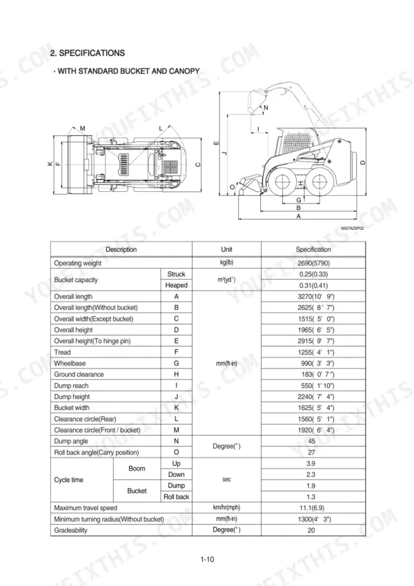
| General | 1-21 | Safety Hints, Machine Specifications (Bucket Capacity and Width, Clearance Circles, Chain Case, Control Method), Engine Data (Compression Ratio, Combustion Chamber Type, Cooling Method), Axial Tandem Piston Pump Data, Maintenance Schedule |
| Hydraulic System Overview and Component Testing | 22-35 | Hydraulic Circuit, Component Testing, HST Pump, Auxiliary Pump, Charge Pump Pressure |
| Self Level Valve and Auxiliary Pump Maintenance | 36-57 | Self Level Valve Structure, Auxiliary Pump Removal and Install, Pump Disassembly and Assembly, Bearing Maintenance |
| HST Pump (Mechanical and Pilot Types) | 58-84 | HST Pump Removal and Install, HST Pump Structure, Charge Pump Options, Filtration Options |
| Travel Motor Maintenance | 85-107 | Travel Motor Removal and Install, Travel Motor Structure, Brake Motor Disassembly, Brake Motor Assembly |
| Main Control Valve and Cylinder Maintenance | 108-148 | Main Control Valve Removal and Install, Spool Disassembly and Assembly, Boom Cylinder Maintenance, Bucket Cylinder Maintenance |
| Electrical System | 149-171 | Component Location, Wiring Diagram, Electrical Component Specification |
| Power Train | 172-177 | Power Train Component, Front and Rear Axle |
| Control | 178-185 | Mechanical Control, Pilot Control, Attachment Holder |
| Troubleshooting | 186-194 | Travel Hydraulics, Boom and Bucket Hydraulic, Power Train, Control, Electrical System |
Quick Reference Specifications
| Specification | Value | Page |
|---|---|---|
| Battery | 1 x 12V x 100~120Ah | p. 12 |
| Starting motor | 12V-2.0kW | p. 13 |
| Tightening torque | 3.7~4.2 kgf·m (26.8~30.4 lbf·ft) | p. 42 |
| Tightening torque for pump bolts | 14.3 kgf·m (103 lbf·ft) | p. 48 |
| Tightening torque for bolts (1st working section) | 14.3 kgf·m (103 lbf·ft) | p. 56 |
| Tightening torque for bolts (2nd working section) | 4.59 kgf·m (33.2 lbf·ft) | p. 56 |
| Hydraulic oil filter change interval | 500hrs | p. 68 |
| Hydraulic fluid filter micron rating | 10 micron | p. 67 |
| Tightening torque for mounting bolt(4) | 23.4 ± 3.5 kgf·m (169 ± 25 lbf·ft) | p. 105 |
| Tightening torque for bolt(1) | 6.9 ± 1.4 kgf·m (49.9 ± 10.1 lbf·ft) | p. 105 |
| Start motor | 12V, 2.0kW | p. 168 |
| Engine Oil Quantity | 9.5 L | p. 13 |