
Part of the Hyundai Repair Manuals.
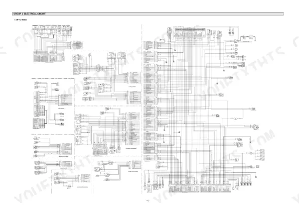
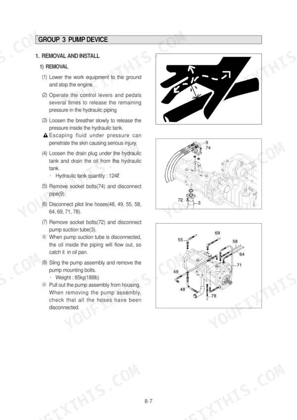
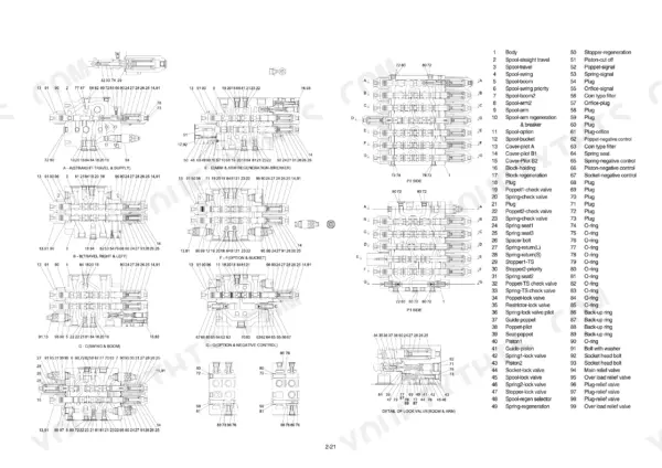
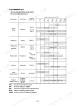
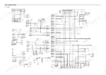
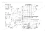
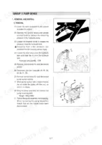
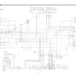
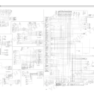
This 573-page Hyundai R140LC-7, R140LCD-7, R140LCM-7 service manual PDF is the full factory shop book for the -7 series hydraulic excavator, from pump device and main control valve to swing drive, travel motors, and RCV controls. Inside: complete hydraulic circuit schematics for the pilot, main, single, and combined operation circuits, plus electrical wiring diagrams with connector pinouts and component locations. You also get a dedicated troubleshooting section for hydraulic, electrical, and mechatronics faults, self-diagnostics for the mode selection and power boost systems, and page after page of tightening and mounting torque tables. Set parking brake release pressure at 6 kgf/cm2 (0.59 MPa), and confirm the high/low speed changeover pilot kicks in at 20 kgf/cm2 (1.96 MPa). No more chasing pressure faults with a gauge and a hunch. Bookmarked and text-searchable on any device; download it and walk straight to your machine.
What's Inside This Hyundai R140LC-7, R140LCD-7, R140LCM-7 Manual
| System | Pages | Key Topics |
|---|---|---|
| General | 11-54 | Safety Hints, Specifications |
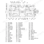
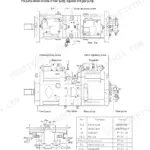
| Structure and Function | 55-156 | Pump Device, Main Control Valve, Swing Device, Travel Device, Rcv Lever, Rcv Pedal |
| Hydraulic System | 157-191 | Hydraulic Circuit, Main Circuit, Pilot Circuit, Single Operation, Combined Operation |
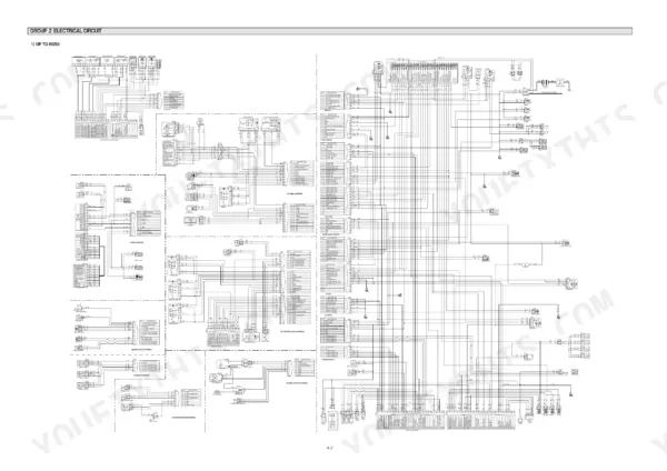
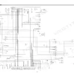
| Electrical System | 192-245 | Component Location, Electrical Circuit, Electrical Component Specification, Connectors |
| Mechatronics System | 246-284 | Outline, Mode Selection System, Automatic Deceleration System, Power Boost System, Travel Speed Control System, Automatic Warming Up Function, Engine Overheat Prevention Function |
| Maintenance Standard | 343-377 | Operational Performance Test, Major Components, Track and Work Equipment |
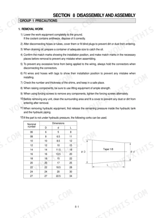
| Disassembly and Assembly | 378-558 | Precaution, Tightening Torque, Pump Device, Main Control Valve, Swing Device, Travel Device, Rcv Lever, Turning Joint |
| Component Mounting Torque | 559-573 | Introduction Guide, Engine System, Electric System, Undercarriage, Structure, Work Equipment |
Quick Reference Specifications
| Specification | Value | Page |
|---|---|---|
| Parking brake release pressure | 6 kgf/cm² (0.59 MPa) | p. 52 |
| High/low speed changeover pilot pressure | 20 kgf/cm² (1.96 MPa) | p. 141 |
| Secondary pressure | 5 to 20.5 kgf/cm² | p. 145 |
| Bypass relief valve | 1.5 kgf/cm2 | p. 161 |
| Check valve(1) | 3.0 kgf/cm2 | p. 161 |
| Bypass valve | 1.5 kgf/cm2 | p. 162 |
| Relief valve | 35 kgf/cm2 | p. 163 |
| Friction plate braking torque | 49.3kgf·m or more | p. 369 |
| Mating plate maximum allowable braking torque | 49.3kgf·m or less | p. 369 |
| Swing bearing upper part mounting bolt | 41.3 ± 6.2 kgf·m | p. 382 |
| Swing bearing lower part mounting bolt | 31.3 ± 4.7 kgf·m | p. 382 |
| Operating weight | 13980 kg | p. 21 |
Hyundai R140LC-7, R140LCD-7, R140LCM-7 Common Problems This Manual Covers
Hyundai R140LC-7 hydraulic functions weak and jerky after pump replacement, boom slow to lift and drops
Bleed the air before condemning your work. Run low idle and cycle each cylinder full stroke several times with no load, then swing slowly to purge the motor. Verify main relief pressure at 330 kgf/cm2 against the spec on page 51, and check the return filter; a plugged element opens its 1.5 kgf/cm2 bypass and dumps unfiltered oil back to tank.
Manual Section: Hydraulic and Mechanical System p. 289Travel dead on one side, opposite track pulls the machine in a circle
Check parking brake release first: tee a gauge into the brake line and confirm 6 kgf/cm2 (0.59 MPa), the release spec on page 52. Verify the high/low changeover pilot signal reaches 20 kgf/cm2. If both check out, pull the travel motor and measure piston assembly axial clearance against the 0.15 mm wear limit on page 368.
Manual Section: Hydraulic and Mechanical System p. 5Swing drags or won't hold on a slope, upper structure creeps under load
Test swing relief settings before tearing into the motor; a stuck relief mimics brake drag. Time a full rotation and compare it to the 13.6 rpm spec on page 51. Inspect the swing bearing mounting bolts while you are up there and torque the upper bolts to 41.3 ± 6.2 kgf·m per the table on page 382.
Manual Section: Hydraulic and Mechanical System p. 382Boom drifts down with a loaded bucket, cylinder shows no external leaks
Run the internal leakage test from the operational performance procedures starting on page 343: warm the oil, raise the boom, and watch for rod movement with controls in neutral. Verify the main relief holds 330 kgf/cm2 before blaming seals. If drift continues, replace the piston seals and inspect the holding valve seat.
Manual Section: Maintenance Standard p. 343Engine oil pressure lamp stays on after warm up at operating temperature
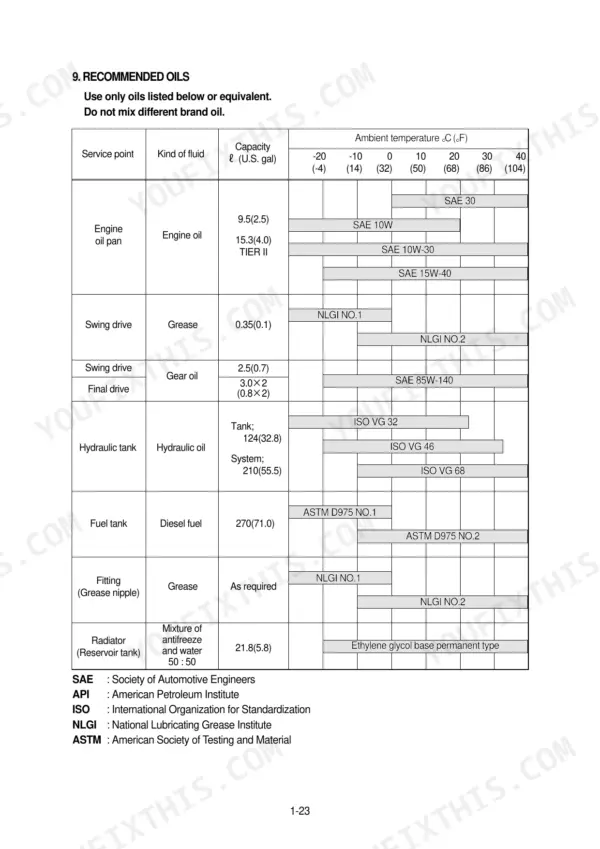
Check oil level on level ground before chasing sensors. Cummins B3.9-C engines take 9.5 L, listed on page 50; top up and replace the oil filter cartridge if the lamp stays on after warm up. Confirm the sender wiring and connectors are tight, then trace the circuit through the troubleshooting steps starting.
Manual Section: Electrical System p. 273Frequently Asked Questions
What is the torque specification for the track roller mounting bolts on a Hyundai R140LC-7?
The tightening torque for the track roller mounting bolts on the R140LC-7 is 29.6 ± 3.2 kgf·m (214 ± 23.1 lbf·ft). p. 382
How do I clear fault codes on a Hyundai R140LC-7 excavator?
To delete all recorded error codes, select the recorded error (TIME Er) display on the cluster, then press the engine and select switch at the same time for 2 seconds or more. The cluster display will change to 'TIME Er : 00', indicating that the CPU controller has deleted all recorded error codes from the memory. p. 259
What is the tightening torque for the main relief valve on the R140LC-7?
The tightening torque for the main relief valve is 8 to 9 kgf·m (57.8 to 65.1 lbf·ft). p. 419
What is the hydraulic tank capacity for the R140LC-7?
The hydraulic tank capacity for the R140LC-7 is 124 liters (32.8 U.S. gal). p. 54
What is the standard engine speed for the R140LC-7 in H-mode?
The standard engine speed for the R140LC-7 in H-mode is 2350 ± 50 rpm. p. 347
Do I get instant access to this Hyundai R140LC-7 Service Manual?
Instant PDF download. You get the full 573-page searchable Service Manual immediately after payment. Open it on your laptop, tablet, or phone right in the shop.
Is printing allowed for this Hyundai R140LC-7 Service Manual?
Yes. Print the sections you need to take out to the shop for your own use. Standard letter or A4 paper works.









Reviews
There are no reviews yet.