
Part of the Hyundai Repair Manuals.
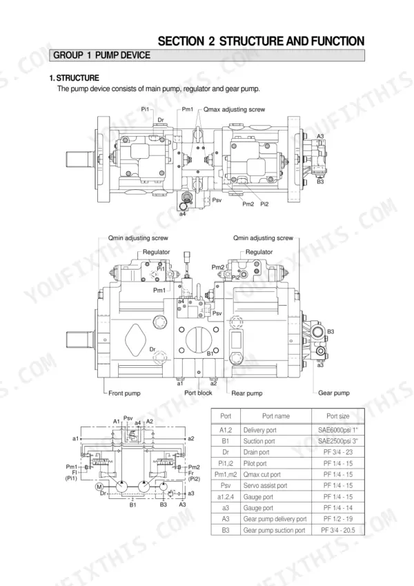
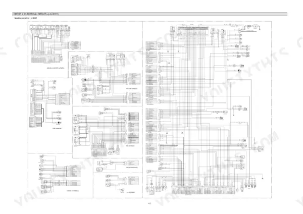
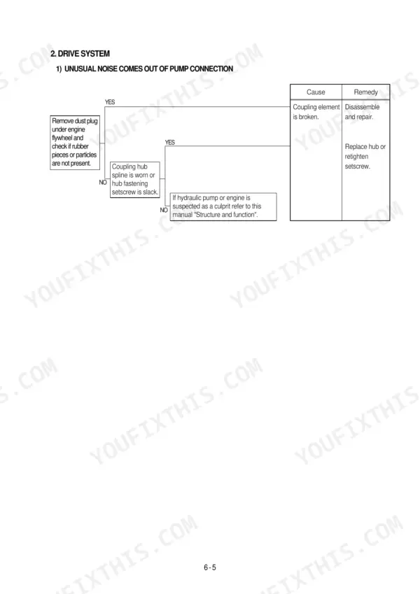
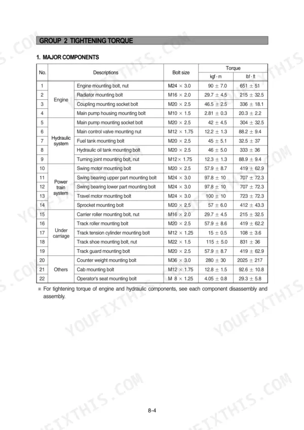
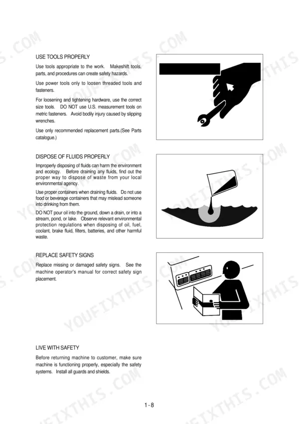
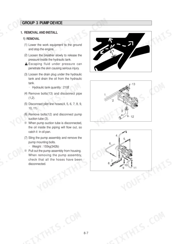
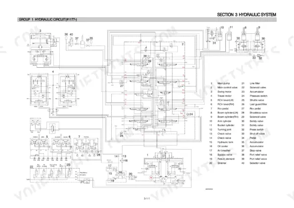
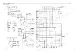
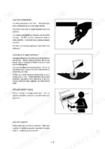
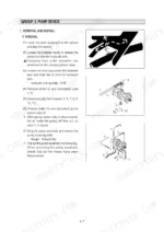
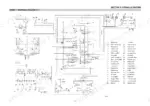
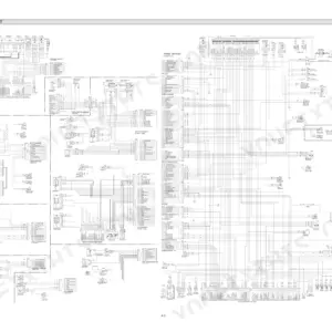
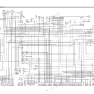
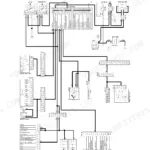
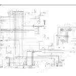
Need the factory answer for your Hyundai R290LC-7? This 626-page Hyundai R290LC-7 service manual PDF covers the hydraulic excavator from safety hints all the way to final component mounting torques. Inside: complete hydraulic circuit schematics with main and pilot circuit routing, electrical wiring diagrams for both standard and Tier II machines, self-diagnostic error code charts, and a full disassembly and assembly section walking you through the pump device, main control valve, swing and travel drives. You get factory numbers, not forum guesses: set the main relief valve to 330 kgf/cm2 (4690 psi) and confirm each pump section flows 260 l/min at rated speed. Chasing an electrical gremlin with a multimeter and a prayer? Bookmarked chapters plus a live text layer let you jump straight to any spec by keyword. Download it, open it on the machine, start wrenching.
What's Inside This Hyundai R290LC-7 Manual
| System | Pages | Key Topics |
|---|---|---|
| General | 1-36 | Safety Hints, Specifications |
| Structure and Function | 37-141 | Pump Device, Main Control Valve, Swing Device, Travel Device, Rcv Lever, Rcv Pedal |
| Hydraulic System | 142-174 | Hydraulic Circuit, Main Circuit, Pilot Circuit, Single Operation, Combined Operation |
| Electrical System | 175-245 | Component Location, Electrical Circuit, Electrical Component Specification, Connectors |
| Mechatronics System | 246-300 | Outline, Mode Selection System, Automatic Deceleration System, Power Boost System |
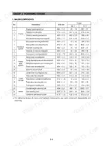
| Maintenance Standard | 367-403 | Operational Performance Test, Major Components, Track and Work Equipment |
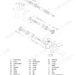
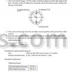
| Disassembly and Assembly | 404-610 | Precaution, Tightening Torque, Pump Device, Main Control Valve, Swing Device, Travel Device, Rcv Lever, Turning Joint |
| Component Mounting Torque | 611-626 | Introduction Guide, Engine System, Electric System, Undercarriage, Structure, Work Equipment |
Quick Reference Specifications
| Specification | Value | Page |
|---|---|---|
| Main relief valve pressure | 330kgf/cm2 (4690psi)[360kgf/cm2 (5120psi)] | p. 34 |
| Maximum pressure | 330kgf/cm2 (4690psi)[360kgf/cm2 (5120psi)] | p. 32 |
| Capacity | 2 x 136.8cc/rev | p. 32 |
| Rated oil flow | 2 x 260 l/min (68.7U.S. gpm/ 57.2U.K. gpm) | p. 32 |
| Main relief valve setting pressure | 330kgf/cm2 | p. 151 |
| Bypass relief valve opening pressure | 1.5kgf/cm2 | p. 146 |
| Bypass check valve setting pressure | 3.0kgf/cm2 | p. 146 |
| Tightening torque (Overload relief valve) | 8~9 kgf·m (57.8~65.1 lbf·ft) | p. 443 |
| Overload relief valve torque | 10~12 kgf·m (72.3~86.8 lbf·ft) | p. 485 |
| Operating Weight | 28900 kg | p. 22 |
| Engine Rated Gross Horsepower | 195 Hp | p. 32 |
| Engine Oil Quantity | 18.9 L | p. 32 |
Hyundai R290LC-7 Common Problems This Manual Covers
Hyundai R290LC-7 all hydraulic functions weak, low pressure across boom, bucket, swing, and travel
Check main relief valve pressure with a gauge on the pump test port. Verify 330 kgf/cm2 standard and 360 kgf/cm2 on power max against the settings on page 151. Adjust the valve if reading low; if it will not hold pressure, replace the cartridge and torque it to 8 to 9 kgf·m with a 32 mm spanner (page 443).
Manual Section: Hydraulic System p. 151Boom, bucket, and right travel underpowered while stick, swing, and left travel work fine
Test the affected pump circuit relief pressure at full stroke against the 330 kgf/cm2 (4690 psi) spec on page 32. Follow the pressure isolation steps starting to separate pump trouble from valve trouble. Swap relief cartridges between pump sections; if the weakness follows the cartridge, adjust or replace it.
Manual Section: Hydraulic and Mechanical SystemBoom drifts down and arm creeps toward the no-load side with pilot controls in neutral
Run the cylinder drift check from the operational performance test section starting on page 367 with the bucket loaded and controls in neutral. Test the overload relief valve opening pressure on the drifting circuit; replace any valve that opens low and torque the new one to 10 to 12 kgf·m (page 485). If drift continues, pull the cylinder and inspect the piston seals for internal leakage.
Manual Section: Maintenance Standard p. 367Hydraulic oil temperature warning lamp and buzzer come on during normal digging
Shut down and let the system cool; the warning trips when oil passes 105°C. Check the hydraulic tank level at the sight gauge and top up before restarting. Clean packed dirt out of the oil cooler and radiator cores with compressed air from the fan side. If it still runs hot, test the cooler bypass check valve, which should hold 3.0 kgf/cm2 (page 146).
Manual Section: Hydraulic System p. 146Hydraulic pump whines under load, functions slow, oil looks cloudy in the tank
Check tank oil level first, then replace the breather element; a starved inlet makes the pump cavitate and aerates the oil. Replace the return filter before its bypass opens at 1.5 kgf/cm2 (page 146). If noise continues with clean fresh oil, tear down the pump and measure piston and shoe play against the 0 to 0.1 mm limit on page 388.
Manual Section: Maintenance Standard p. 388Frequently Asked Questions
How do I delete recorded error codes on a Hyundai R290LC-7 monitor?
To delete all recorded error codes, select the recorded error (TIME Er) display on the cluster. Then, press the engine and select switch at the same time for 2 seconds or more. The cluster display will change to 'TIME Er : 00', indicating that the CPU controller has deleted all recorded error codes from the memory. p. 259
What do Hyundai R290LC-7 error codes 35, 36, 37, 38, 39, and 40 mean?
Error code 35 indicates controller input voltage is over 38V. Code 36 is a communication error with the cluster. Code 37 means the engine speed sensor circuit is open or shorted to ground. Code 38 is an anti-restart relay circuit open or shorted to ground. Code 39 means the accel actuator does not stop at a target position. Code 40 indicates a difference of more than 500rpm between target speed and actual speed. p. 295
What is the self-diagnostic procedure for Hyundai R290LC-7?
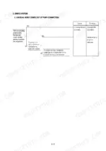
The self-diagnostic mode is selected by touching the SELECT switch 2 times while pressing the BUZZER STOP switch on the cluster. The system will then display current or recorded error codes on the cluster LCD. p. 259
What is the tightening torque for the main relief valve on the R290LC-7?
The tightening torque for the main relief valve is 8 to 9 kgf·m (57.8 to 65.1 lbf·ft). p. 443
What is the standard engine speed for the H-mode on the R290LC-7?
The standard engine speed for the H-mode is 2050 ± 50 rpm. p. 371
Is this Hyundai R290LC-7 Service Manual a digital download?
Instant PDF download. You get the full 626-page searchable Service Manual immediately after payment. Open it on your laptop, tablet, or phone right in the shop.
Can I print this Hyundai R290LC-7 manual?
Yes. Print the pages or sections you need for your own shop use. Any standard printer works.








Reviews
There are no reviews yet.