
Part of the Hyundai Repair Manuals.
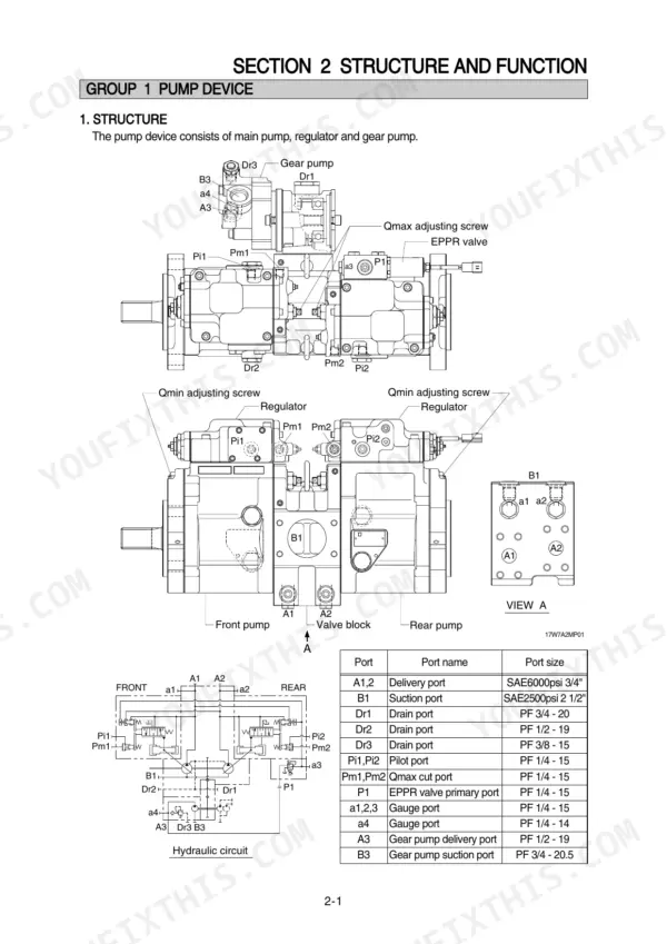
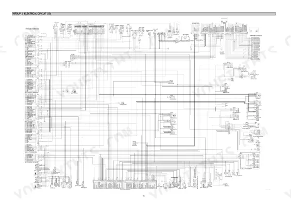
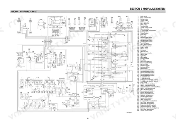
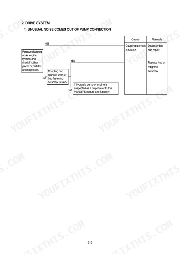
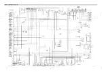
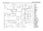
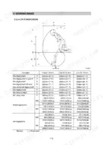
This 617-page Hyundai R170W-7A Shop Manual PDF is aimed at one machine: your R170W-7A wheel excavator, from pump device to rear axle differential. You get full hydraulic schematics for the main circuit, pilot circuit, and combined operation, plus wiring diagrams with connector pinouts and component locations. Inside: mechatronics troubleshooting for the self-diagnostic system, step-by-step teardown procedures for the pump, main control valve, swing motor, travel motor, transmission, steering valve, and both axles, and mounting torque charts for every system. Set the pilot relief valve to 40 kgf/cm2, and check that the bypass check valve is set at 4.5 kgf/cm2 (64 psi) before you blame the pump. A wheel excavator earns nothing parked in the yard. Bookmarked with a full text layer; pull it up on your phone, jump to the section, and start wrenching.
What's Inside This Hyundai R170W-7A Manual
| System | Pages | Key Topics |
|---|---|---|
| General | 1-35 | Safety Hints, Specifications |
| Structure and Function | 36-124 | Pump Device, Main Control Valve, Swing Device, Travel Motor, Rcv Lever, Accelerator Pedal, Brake Pedal, Transmission |
| Hydraulic System | 125-177 | Hydraulic Circuit, Main Circuit, Pilot Circuit, Single Operation, Combined Operation |
| Electrical System | 178-232 | Component Location, Electrical Circuit, Electrical Component Specification, Connectors |
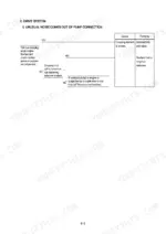
| Mechatronics System | 233-266 | Outline, Mode Selection System, Automatic Deceleration System, Power Boost System, Travel Speed Control System |
| Maintenance Standard | 315-343 | Operational Performance Test, Major Components, Track and Work Equipment |
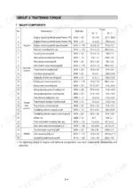
| General Precautions and Tightening Torque | 344-350 | Removal Work, Installation Work, Tightening Torque Charts, Pipe and Hose Connections |
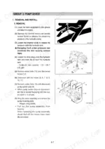
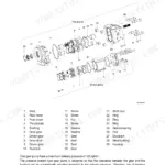
| Pump Device Disassembly and Assembly | 351-373 | Main Pump Removal, Main Pump Installation, Regulator Structure, Regulator Disassembly, Regulator Assembly |
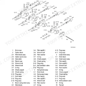
| Main Control Valve Disassembly and Assembly | 374-387 | Main Control Valve Removal, Main Control Valve Installation, Spool Disassembly, Holding Valve, Relief Valve |
| Swing Device Disassembly and Assembly | 388-410 | Swing Motor Removal, Swing Motor Installation, Swing Motor Disassembly, Swing Motor Assembly, Reduction Gear Disassembly, Reduction Gear Assembly |
| Travel Motor Disassembly and Assembly | 411-434 | Travel Motor Removal, Travel Motor Installation, Motor Unit Structure, Regulator Structure, Counter-Balance Valve, Sealing the Drive Shaft |
| Steering Valve Disassembly and Assembly | 435-459 | Steering Valve Removal, Steering Valve Installation, Steering Valve Disassembly, Steering Valve Assembly, Tightening Torque |
| Front and Rear Axle Disassembly and Assembly | 460-554 | Front Axle Removal, Rear Axle Removal, Differential Disassembly, Differential Assembly, Input Flange, Pivot Bearing |
| Work Equipment Disassembly and Assembly | 555-601 | Rcv Lever Disassembly, Rcv Lever Assembly, Bucket Cylinder, Arm Cylinder, Boom Cylinder, Dozer Cylinder |
| Component Mounting Torque | 602-617 | Introduction Guide, Engine System, Electric System, Power Train System, Structure, Work Equipment |
Quick Reference Specifications
| Specification | Value | Page |
|---|---|---|
| Bypass check valve setting pressure | 4.5kgf/cm2 (64psi) | p. 128 |
| Bypass relief valve opening pressure | 1.5kgf/cm2 (21psi) | p. 128 |
| Voltage | 10~12.5V | p. 184 |
| Battery | 12V 80Ah | p. 201 |
| Starter | 24V 5.0kW | p. 206 |
| Fuel filter element interval | 500hr | p. 263 |
| Drain filter cartridge interval | 250hr | p. 263 |
| CAN communication resistance | 120 Ω | p. 293 |
| Starter motor voltage | 20~30V | p. 300 |
| Turning joint seal set - Slipper ring | 1.5mm (0.059in) narrower than seal groove | p. 341 |
| Turning joint seal set - Worn limit | 0.5mm (0.02in) ~ 1.5mm (0.059in) | p. 341 |
Hyundai R170W-7A Common Problems This Manual Covers
Hyundai R170W-7A boom and arm move slow or jerky, bucket loses power under load
Check hydraulic oil level and condition first; milky or dark oil means water or wear metal contamination. Test pilot pressure against the 40 kgf/cm2 relief setting on page 130, then verify main relief pressure reaches 330 kgf/cm2. Low readings point to pump wear, so follow the diagnostic steps starting before pulling the pump.
Manual Section: Hydraulic and Mechanical System TroubleshootingEngine cranks slowly or refuses to start, starter relay clicking in cold weather
Load test both 12V 80Ah batteries and clean the terminals; the series pair must deliver a full 24V to the starter circuit, per the checks on page 301. Measure voltage at the starter B terminal while cranking. If the 24V 5.0kW starter still drags with good batteries, pull it and bench test before replacing.
Manual Section: Electrical System Troubleshooting p. 301Loss of power under load with black smoke from exhaust when digging
Replace the fuel filter element if it is past the 500 hour interval listed on page 263, and drain sediment from the fuel tank. Pull the air cleaner element and inspect it against a light; replace it if clogged. Check for air leaks between the filter head and injection pump before condemning the engine.
Manual Section: Mechatronics System Troubleshooting p. 263Boom drifts down with a loaded bucket, clunks when lift command starts
Test main relief pressure first; it should hold 330 kgf/cm2 per the spec on page 32. Swap the boom holding valve with a known good unit to isolate the leak path. If drift stays, reseal the boom cylinder using the procedure starting on page 555, and inspect pivot pins and bushings for wear.
Manual Section: Work Equipment Disassembly and Assembly p. 555Warning lights flicker on cluster and gauges drop out intermittently while operating
Check CAN bus resistance across the communication lines; a healthy network reads 120 ohms, shown on page 293. Measure ground resistance from connector CN-51 pin 16 to chassis, maximum 1 ohm per page 294. Clean corroded connectors, apply dielectric grease, and wiggle test harness sections while watching the cluster for dropouts.
Manual Section: Electrical System Troubleshooting p. 293Frequently Asked Questions
What do the error codes on a Hyundai R170W-7A mean?
Error codes indicate specific electrical or sensor malfunctions. For example, error code 1 indicates a short circuit in the accel actuator system, while error code 34 indicates the controller input voltage is below 18V. A full table of error codes and their descriptions can be found on pages 246 and 247. p. 246
How do I clear fault codes on a Hyundai R170W-7A excavator?
To clear recorded error codes, open the 'Diagnosis' menu on the cluster display, select 'Recorded Error', and then choose the option to delete all errors. The system will prompt you to confirm the deletion. p. 245
What are the torque specifications for the swing motor mounting bolts?
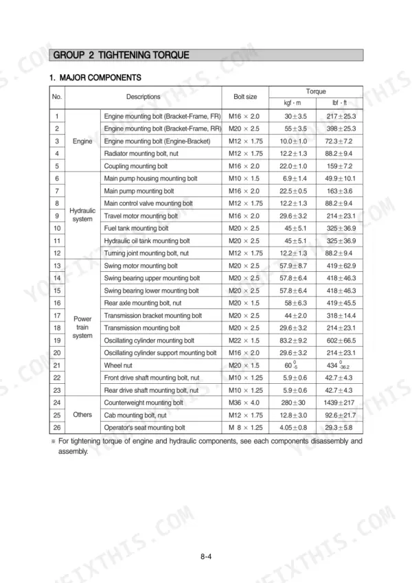
The torque specification for the swing motor mounting bolts (M20 x 2.5) is 57.9 ± 8.7 kgf·m (419 ± 62.9 lbf·ft). p. 348
What is the engine oil capacity for the R170W-7A?
The engine oil quantity for the Mitsubishi D04FD-TAA engine is 18.5 liters (4.9 U.S. gal). p. 31
What is the tightening torque for the main pump mounting bolts?
The tightening torque for the main pump mounting bolts (M16 x 2.0) is 22.5 ± 0.5 kgf·m (163 ± 3.6 lbf·ft). p. 348
Do I get instant access to this Hyundai R170W-7A Shop Manual?
You get a 617-page searchable PDF that downloads instantly after checkout. Open it on your laptop, tablet, or phone, and bring it right to the shop floor.
Can I print pages of this Hyundai R170W-7A manual for my own shop?
Yes. Print individual pages or full chapters for your own shop use, on letter or A4 paper.






Reviews
There are no reviews yet.