
Part of the Hyundai Repair Manuals.
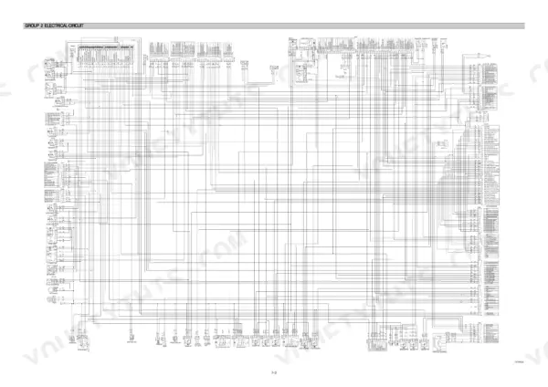
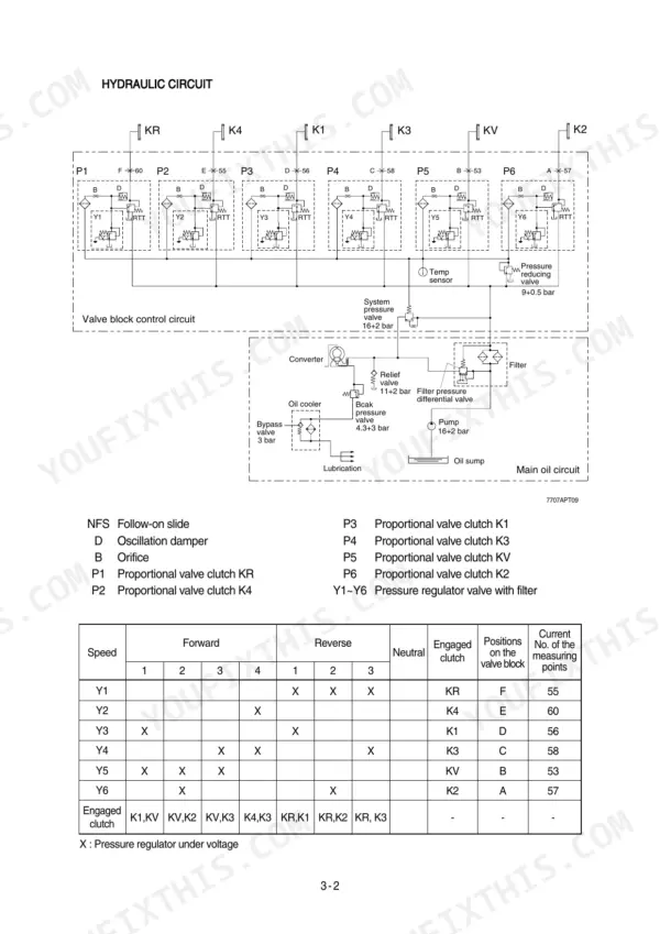
All 665 pages of this Hyundai HL770-7A, HL770XTD-7A service manual PDF point at one job: keeping both wheel loader variants running to factory spec. Inside you get complete electrical circuit diagrams with connector pinouts, hydraulic schematics for the brake, steering, and work equipment circuits, and full transmission fault code tables for the electro-hydraulic shift control. Step-by-step teardown procedures cover the torque converter, both Volvo and ZF axles, and the differential, right down to brake hydraulics leakage testing. The main pump tops out at 150 kgf/cm² delivery pressure; torque the engine mounting bolts to 100 ± 15 kgf·m and change the hydraulic oil filter every 250 operating hours. A loader sitting dead costs you money every shift. Bookmarked and searchable by keyword; open it on a phone or tablet and walk straight to the machine.
What's Inside This Hyundai HL770-7A, HL770XTD-7A Manual
| System | Pages | Key Topics |
|---|---|---|
| General | 11-36 | Safety Hints, Specifications, Operational Checkout Record Sheet |
| Engine | 37-44 | Structure and Function |
| Power Train System Overview and Torque Converter | 45-49 | Power Train Component Overview, Torque Converter Function, Hydrodynamic Torque Converter |
| Transmission Layout and Operation | 50-66 | Transmission Layout, Forward and Reverse Gear Operation, Electro-Hydraulic Shift Control, Gear Selector, Aeb Mode |
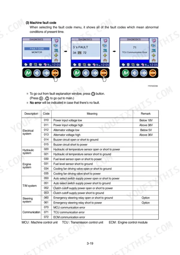
| Transmission Fault Codes and Troubleshooting | 67-112 | Engine Fault Codes, Transmission Fault Codes, Operating Modes, Axle Operation, Differential Operation, Final Drive Section |
| Power Train Operational Checks and Troubleshooting | 113-123 | Power Train Operational Checks, Transmission Troubleshooting, Differential and Axle Troubleshooting, Drive Line Troubleshooting |
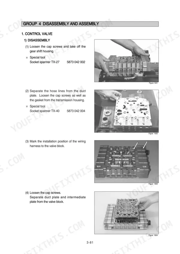
| Transmission Tests, Adjustments, and Disassembly | 124-218 | Clutch Cut-Off Pressure Switch Test, Transmission Measuring Points, Control Valve Disassembly and Assembly, Transmission Disassembly and Assembly |
| Axle Disassembly, Assembly, and Testing | 219-363 | Volvo Axle Disassembly and Assembly, Zf Axle Disassembly and Assembly, Brake Tube Disassembly and Assembly, Differential Assembly, Brake Hydraulics Leakage Test |
| Brake System | 364-411 | Structure and Function, Operational Checks and Troubleshooting, Tests and Adjustments, Disassembly and Assembly |
| Steering System | 412-509 | Structure and Function, Operational Checks and Troubleshooting, Tests and Adjustments, Disassembly and Assembly |
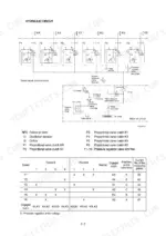
| Work Equipment | 510-591 | Structure and Function, Operational Checks and Troubleshooting, Tests and Adjustments, Disassembly and Assembly |
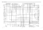
| Electrical System | 592-665 | Component Location, Electrical Circuit, Monitoring System, Electrical Component Specification, Connectors, Troubleshooting |
Quick Reference Specifications
| Specification | Value | Page |
|---|---|---|
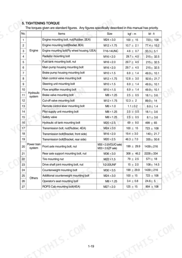
| Engine mounting bolt, nut(Rubber, 2EA) | 100 ± 15 kgf·m | p. 30 |
| Inductive transmitter n-Engine(9) setting dimension X | 0.5 +0.3 mm | p. 228 |
| Main pump maximum delivery pressure | 150 kgf/cm² | p. 372 |
| Hydraulic oil filter replacement interval | 250 operating hours | p. 567 |
| Throttle check valve in PP-connection tightening torque | 1 ± 0.3 kgf·m | p. 469 |
| Steering unit mounting bolt | 6.9 ± 1.4 kgf·m | p. 30 |
| Center pivot pin bearing serviceable limit clearance | 0.8 mm | p. 507 |
| Fuel filter replacement interval | 250 operating hours | p. 567 |
| Transmission oil overheating warning temperature | 107°C | p. 614 |
| Engine Oil Quantity | 23 L | p. 27 |
| Main Relief Valve Pressure | 210 kgf/cm2 | p. 28 |
| Engine High Idling Speed | 2200 rpm | p. 27 |
Hyundai HL770-7A, HL770XTD-7A Common Problems This Manual Covers
Hyundai HL770-7A transmission overheating, temperature gauge in red, warning alarm during load and carry work
Check transmission oil level first; the system holds 50 L (page 33). The temperature gauge red range starts at 107°C (page 614), so shut down and let it cool above that. Inspect the cooler and lines for restriction or crushed hoses, then run the power train operational checks starting on page 113 to isolate an internal fault.
Manual Section: Power Train Operational Checks and Troubleshooting p. 113Transmission error lamp on with fault code showing on LCD, gears won't change from dash selector
Stop the machine and shut the engine down before anything else. Record the code from the LCD, then match it against the fault code tables starting on page 67 for the reaction and repair steps. If the TCU shows no selector signal, check the engine speed sensor setting dimension of 0.5 +0.3 mm before condemning the controller.
Manual Section: Transmission Fault Codes and Troubleshooting p. 67Hydraulic pump whining under load, bucket and boom slow, oil runs hot after an hour
Check the oil level and suction strainer first; a plugged screen or pinched suction line starves the pump and mimics a worn rotating group. Bleed air from the system, then verify main relief valve pressure against the 210 kgf/cm2 spec on page 28. Replace the hydraulic oil filter every 250 operating hours to keep debris out.
Manual Section: Work Equipment Troubleshooting p. 510Shock through the frame when steering or reversing, steering feels loose and wanders
Measure center pivot pin bearing clearance; the serviceable limit is 0.8 mm per page 507, and worn pins hammer the frame on every direction change. Check the steering unit mounting bolts and torque them to 6.9 ± 1.4 kgf·m using the chart on page 30. Inspect the drive shaft and pivot capscrews while you are under there.
Manual Section: Steering System Troubleshooting p. 412Error code 418 on cluster, engine runs rough, water sitting in the fuel filter bowl
Drain the water separator immediately; code 418 means the water-in-fuel sensor has tripped. Replace the fuel filter if it is due, then bleed the system and clear the code. Check the engine fault code definitions starting on page 67 if the lamp returns after draining.
Manual Section: Engine Fault Codes p. 67Frequently Asked Questions
What are the torque specifications for the engine mounting bolts on the Hyundai HL770-7A?
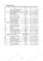
The engine mounting bolts (Rubber, 2EA) require a tightening torque of 100 ± 15 kgf·m (723 ± 108 lbf·ft). The engine mounting bolts (Bracket, 8EA) require 10.7 ± 2.1 kgf·m (77.4 ± 15.2 lbf·ft), and the engine mounting bolts (Fly wheel housing, 12EA) require 4.6 ± 0.7 kgf·m (33.3 ± 5.1 lbf·ft). p. 30
How do I perform the hydraulic brake bleeding procedure on the Hyundai HL770-7A?
Two people are required to bleed the brake system. Put a clear plastic tube on bleed screw (B) to route low to the hydraulic oil tank filler tube or container (A). Start the engine and run at low idle, then push and hold the brake pedal down until the procedure is complete. If bubbles continue for more than 2 minutes, stop and check for problems. p. 405
What is the recommended oil for the engine oil pan on the Hyundai HL770-7A?
The recommended oil for the engine oil pan depends on the ambient temperature. For temperatures between -20°C and 40°C, SAE 15W-40 is recommended. For temperatures between -10°C and 30°C, SAE 10W-30 is recommended. For temperatures between -20°C and 10°C, SAE 10W is recommended, and for temperatures between 10°C and 40°C, SAE 30 is recommended. p. 33
What is the standard value for the boom cylinder drift test on the Hyundai HL770-7A?
The standard value for the retraction of the boom cylinder rod during the 15-minute drift test is 40mm or less. p. 561
What is the tightening torque for the main control valve mounting bolts on the Hyundai HL770-7A?
The tightening torque for the main control valve mounting bolts (M12 x 1.75) is 12.8 ± 3.0 kgf·m (92.6 ± 21.7 lbf·ft). p. 30
Is this Hyundai HL770-7A Service Manual a digital download?
You download the Service Manual yourself: 665 pages, searchable PDF, available immediately. Keep a copy on every device you use.
Is this Hyundai HL770-7A Service Manual printable?
Yes. Print the pages you need for the job in your own shop, and bin them when they get greasy.






Reviews
There are no reviews yet.