
Part of the Hyundai Repair Manuals.
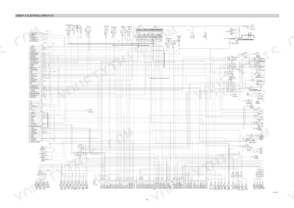
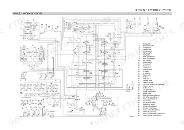
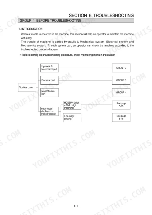
All 490 pages of this Hyundai R210NLC-9 Service Manual PDF focus on one machine: your R210NLC-9 hydraulic excavator, from the pump device to the turning joint. You get complete hydraulic schematics tracing the main and pilot circuits through single and combined operation, plus wiring diagrams with component locations, connector pinouts, and electrical component specs. A full troubleshooting section works through hydraulic, electrical, and mechatronics faults, and the disassembly chapter steps you through the pump, main control valve, swing device, travel motor, and boom, arm, and bucket cylinders. Set the main relief at 30 kgf/cm2, and check the return filter bypass relief at 1.5 kgf/cm2 before you condemn the pump. No more chasing pressure drops with borrowed numbers. Bookmarked and keyword-searchable; pull it up on your tablet beside the machine and start wrenching.
What's Inside This Hyundai R210NLC-9 Manual
| System | Pages | Key Topics |
|---|---|---|
| General | 1-36 | Safety Hints, Specifications |
| Structure and Function | 37-116 | Pump Device, Main Control Valve, Swing Device, Travel Motor, Rcv Lever, Rcv Pedal |
| Hydraulic System | 117-148 | Hydraulic Circuit, Main Circuit, Pilot Circuit, Single Operation, Combined Operation |
| Electrical System | 149-200 | Component Location, Electrical Circuit, Electrical Component Specification, Connectors |
| Mechatronics System | 201-257 | Outline, Mode Selection System, Automatic Deceleration System, Power Boost System, Travel Speed Control System, Automatic Warming Up System, Engine Overheat Prevention System |
| Maintenance Standard | 328-362 | Operational Performance Test, Major Components, Track and Work Equipment |
| Disassembly and Assembly | 363-475 | Precaution, Tightening Torque, Pump Device, Main Control Valve, Swing Device, Travel Device, Rcv Lever, Turning Joint |
| Component Mounting Torque | 476-490 | Introduction Guide, Engine System, Electric System, Undercarriage, Structure, Work Equipment |
Quick Reference Specifications
| Specification | Value | Page |
|---|---|---|
| relief set pressure | 30 kgf/cm2 | p. 80 |
| Relief valve | 40kgf/cm2 | p. 122 |
| Bypass relief valve (in full-flow filter) | 1.5 kgf/cm2 | p. 120 |
| Check valve (1) | 3.0 kgf/cm2 | p. 120 |
| Check valve | 1.5 kgf/cm2 | p. 121 |
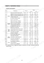
| Initial tightening torque | 78 ± 8 kgf·m | p. 360 |
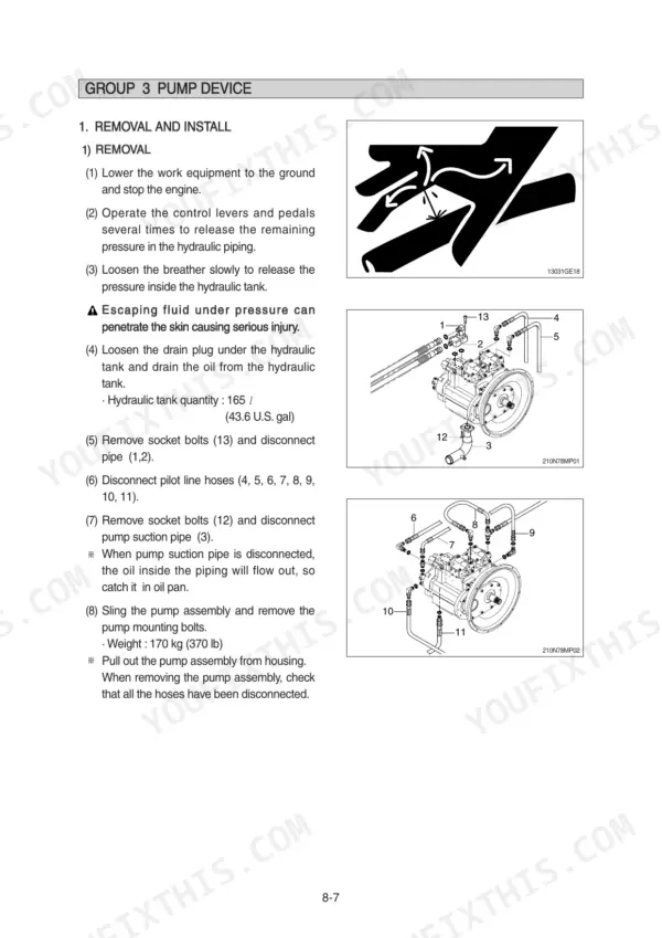
| Hydraulic tank quantity | 165 L (43.6 U.S. gal) | p. 370 |
| Socket head bolt (Bucket cylinder, Item 23, M16) | 23 ± 2.0 kgf·m (166 ± 14.5 lbf·ft) | p. 452 |
| Socket head bolt (Bucket cylinder, Item 31, M10) | 5.4 ± 0.5 kgf·m (39.1 ± 3.6 lbf·ft) | p. 452 |
| Boom cylinder mounting bolt (Item 1, M10x1.5) | 3.2 ± 0.3 kgf·m | p. 484 |
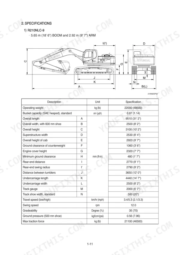
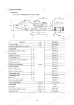
| Operating weight | 22000 kg | p. 23 |
| Travel speed (low/high) | 3.4/5.3 km/hr | p. 23 |
Hyundai R210NLC-9 Common Problems This Manual Covers
Hyundai R210NLC-9 all hydraulic functions weak, boom arm and bucket slow under load
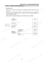
Check pump output pressure at the test ports with the engine at full throttle and a circuit stalled over relief. Compare readings to the main pump maximum in the specification table in the General section. If pressure is low on every function, adjust or replace the main relief valve, then work the diagnostic procedure steps starting before condemning the pump.
Manual Section: General Troubleshooting Introduction p. 23Boom drifts down slowly with control lever in neutral and machine parked
Measure boom drop over five minutes with a loaded bucket, then compare against the operational performance test limits in the Maintenance Standard section starting on page 328. If drift exceeds spec, pull and reseal the boom cylinder, and torque the piston lock nut to the value in the Disassembly and Assembly tightening-torque chart during reassembly.
Manual Section: Maintenance Standard p. 328Hydraulic oil looks cloudy or foamy, cylinders act spongy and jerky
Drain the tank completely and inspect the oil for water; the system takes 165 L (43.6 U.S. gal) per page 370. Replace the return filter, since a plugged element opens the 1.5 kgf/cm2 bypass relief shown on page 120 and sends unfiltered oil to tank. Clean the tank breather and check suction line fittings for air leaks.
Manual Section: Hydraulic System p. 120Machine pulls to one side, travel underpowered on left or right track only
Swap the travel pilot hoses side to side at the control valve to isolate the fault; if the weak side moves, chase the pump and valve circuit, not the motor. Test travel relief pressure against the spec table in the General section. Inspect the turning joint seals using the Disassembly and Assembly procedures starting on page 363.
Manual Section: Hydraulic and Mechanical System Troubleshooting p. 23Hydraulic oil temperature climbs after an hour of steady digging
Clean the oil cooler core with compressed air blown opposite the fan flow, and straighten any crushed fins. Verify oil level and condition; the tank holds 165 L per page 370, and low or degraded oil runs hot fast. Check fan belt tension, then confirm no relief valve is stuck partially open and dumping flow to tank as heat.
Manual Section: Hydraulic System p. 370Frequently Asked Questions
What does the MCU communication error mean on a Hyundai R210NLC-9?
A communication error (HCESPN 840, FMI 2) indicates a failure in the communication between the MCU and the cluster. This can be caused by a defective cluster, a defective MCU, or a disconnection/poor contact in the wiring harness between the MCU and the cluster (the manual traces the path through CN-56, CN-5 and CN-51). p. 283
How do you reset the error codes on a Hyundai R210NLC-9?
You can delete logged faults using the 'Delete logged fault' menu in the cluster. Navigate to the 'Monitoring' menu, select 'Delete logged fault', and confirm the deletion when prompted to clear the stored error codes from the MCU memory. p. 215
What are the replacement specifications for the hydraulic oil return filter?
The hydraulic oil return filter has a recommended replacement interval of 1000 hours. p. 250
What is the tightening torque for the counterweight mounting bolts?
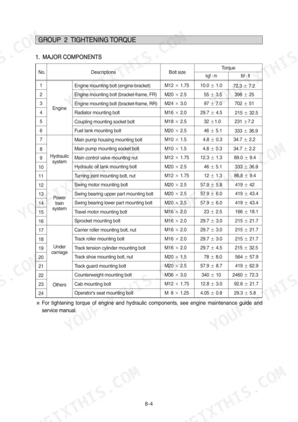
The counterweight mounting bolts (M36 x 3.0) should be tightened to a torque of 340 ± 10 kgf·m (2460 ± 72.3 lbf·ft). p. 367
What is the standard engine speed for the P mode in the R210NLC-9?
The standard engine speed for P mode is 1950 ± 50 rpm at load and unload conditions. p. 332
What exactly do I receive with this Hyundai R210NLC-9 Service Manual?
A 490-page Service Manual in searchable PDF format, available the moment you complete checkout. View on computer, tablet, or phone, with no shipping wait.
Can I print just the pages I need from this Hyundai R210NLC-9 manual?
Yes. Print the pages or sections you need for your own shop use. Any standard printer works.








Reviews
There are no reviews yet.