
Part of the Hyundai Repair Manuals.
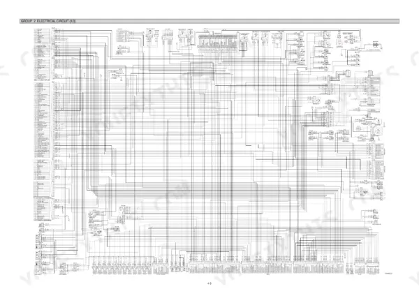
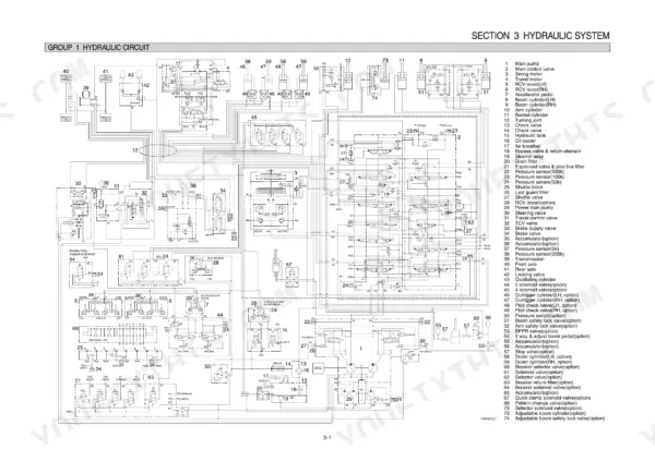
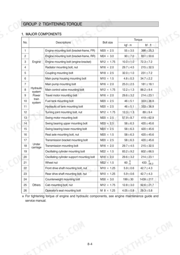
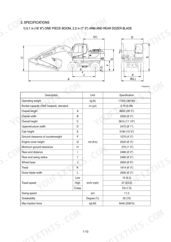
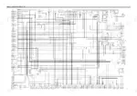
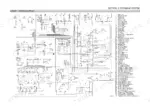
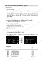
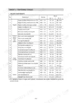
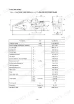
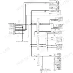
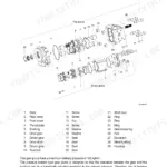
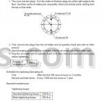
Need the factory data for your Hyundai R170W-9 wheeled excavator? This 682-page Hyundai R170W-9 service manual PDF covers the whole machine, from the main pump and control valve to the powershift transmission, front and rear axles, and every work equipment cylinder. Inside: factory hydraulic circuit schematics, electrical wiring diagrams with connector pinouts, page after page of troubleshooting charts for the hydraulic, electrical, and mechatronics systems, and tightening torque tables for every mounting bolt. You also get the self-diagnostic system breakdown for chasing fault codes right on the monitor. Main relief pressure sits at 350 kgf/cm2 and the MCU raises it to 380 kgf/cm2 under power boost; pilot pressure is specced at 40 kgf/cm2. No more chasing wiring faults with a multimeter and a prayer. Bookmarked with a full text layer: search any spec, jump to any section, fix the machine.
What's Inside This Hyundai R170W-9 Manual
| System | Pages | Key Topics |
|---|---|---|
| General | 1-33 | Safety Hints, Specifications |
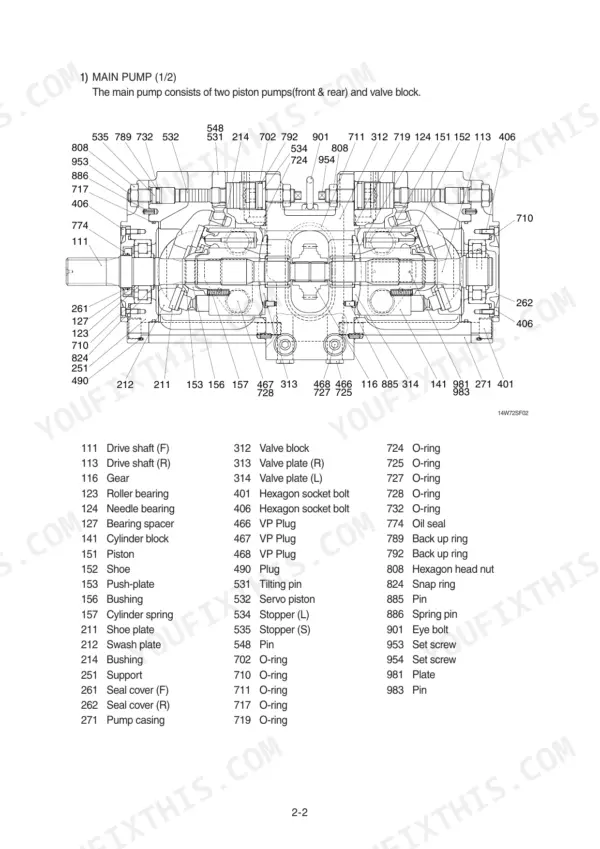
| Structure and Function | 34-119 | Pump Device, Main Control Valve, Swing Device, Travel Motor, Rcv Lever, Accelerator Pedal, Brake Pedal, Transmission |
| Hydraulic System | 120-152 | Hydraulic Circuit, Main Circuit, Pilot Circuit |
| Electrical System | 153-208 | Component Location, Electrical Circuit |
| Mechatronics System | 209-241 | Outline, Mode Selection System, Automatic Deceleration System |
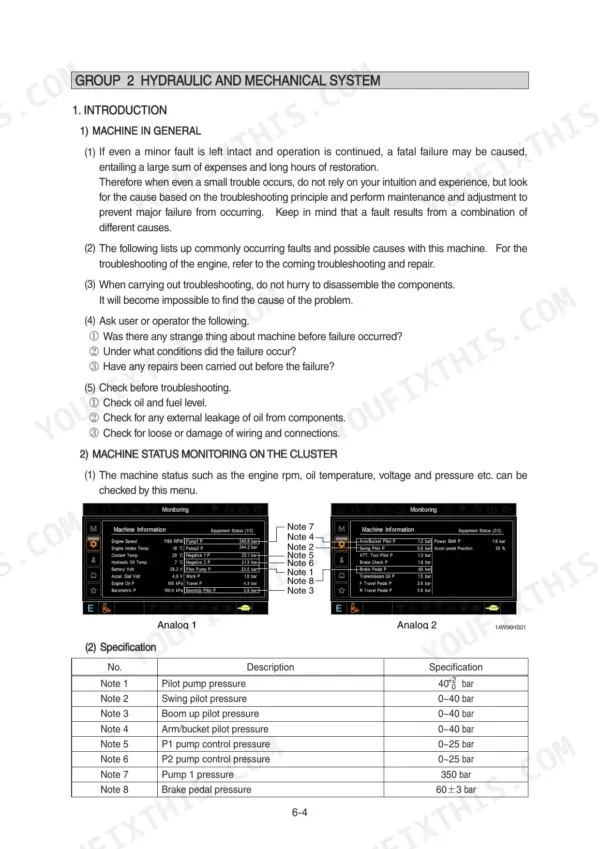
| Troubleshooting | 242-322 | Before Troubleshooting, Hydraulic and Mechanical System, Electrical System, Mechatronics System |
| Maintenance Standard | 323-351 | Operational Performance Test, Major Components, Work Equipment |
| General Precautions and Tightening Torque | 352-358 | Removal Work, Installation Work, Tightening Torque Charts, Pipe and Hose Connections |
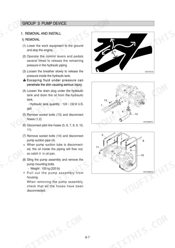
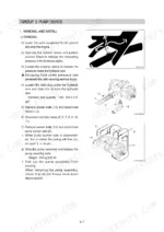
| Pump Device | 359-381 | Removal and Installation, Main Pump Structure, Regulator Disassembly, Assembly Procedures |
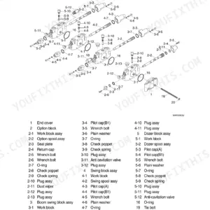
| Main Control Valve | 382-396 | Removal and Installation, Main Control Valve Structure, Disassembly of Spools, Holding Valve Operation |
| Swing Device | 397-411 | Swing Motor Structure, Reduction Gear Disassembly, Swing Parking Brake, Maintenance Standards |
| Transmission | 412-444 | Reduction Gear Assembly, Powershift Transmission, Downshift Interlock, Brake and Clutch Maintenance |
| Front and Rear Axles | 445-582 | Axle Removal, Steering Cylinder, Differential Assembly, Brake Lining Wear Test |
| Work Equipment | 583-666 | Bucket Cylinder, Arm Cylinder, Boom Cylinder, Dozer and Outrigger Cylinders |
| Component Mounting Torque | 667-682 | Introduction Guide, Engine System, Electric System, Power Train System, Structure, Work Equipment |
Quick Reference Specifications
| Specification | Value | Page |
|---|---|---|
| Main relief valve setting pressure | 350 kgf/cm2 | p. 128 |
| Main relief valve setting pressure (power boost) | 380 kgf/cm2 | p. 128 |
| Bypass relief valve opening pressure (full-flow filter) | 1.5 kgf/cm2 | p. 123 |
| Drain filter bypass relief valve opening pressure | 1.5 kgf/cm2 | p. 124 |
| Battery | 12V × 100Ah (2EA) | p. 181 |
| Fuse box | 30A | p. 177 |
| Air cleaner resistance | MAX 1Ω | p. 271 |
| Load check valve plug tightening torque | 6~7 kgf·m (43.4~50.6 lbf·ft) | p. 394 |
| Negative control relief valve plug tightening torque | 8~9 kgf·m (57.8~65.1 lbf·ft) | p. 394 |
| Tightening torque for M8x1.25 | 2.5±0.5 kgf·m | p. 669 |
| Operating weight | 17300 kg | p. 22 |
| Swing speed | 11.0 rpm | p. 22 |
Hyundai R170W-9 Common Problems This Manual Covers
Hyundai R170W-9 all hydraulic functions weak, slow, or unable to build normal pressure
Check main pump delivery pressure at the test port first. Verify the main relief valve holds 350 kgf/cm2, detailed on page 128; power boost should reach 380 kgf/cm2. If the setting drifts or hunts, remove the valve, replace all O-rings and back-up rings, then torque it to 8~9 kgf·m (57.8~65.1 lbf·ft) per page 394.
Manual Section: Hydraulic System p. 128Boom or arm drifts down slowly when the control lever sits in neutral
Test cylinder internal leakage by isolating the circuit under load, then work through the boom and arm drift procedure starting. Inspect the overload relief and holding valves in the main control valve for scored seats. Replace all O-rings, back-up rings and seals (100% replacement per page 343) and torque the overload relief valve to 8~9 kgf·m.
Manual Section: Hydraulic and Mechanical System TroubleshootingEngine cranks slowly or won't start, intermittent electrical faults and dead gauges
Check both 12V, 100Ah batteries; the spec on page 181 calls for a specific gravity check, so test each cell and replace any weak battery as a pair. Inspect the 30A fuses in the fuse box, then clean and tighten ground connections. Trace intermittent faults against the wiring diagram before condemning components.
Manual Section: Electrical System p. 181Air cleaner warning light on, engine down on power and running hot under load
Remove the air filter element and inspect it against a light; replace it rather than blowing it out if it has been serviced repeatedly. Test the air cleaner sensor circuit for resistance, MAX 1 ohm per page 271. Clean debris from the radiator and oil cooler cores, and confirm oil level against the 24 L engine capacity.
Manual Section: Electrical System Troubleshooting p. 271Pilot controls feel dead or sluggish, attachments respond late after lever input
Verify pilot circuit pressure against the 40 kgf/cm2 relief setting shown on page 125. If pressure reads low, replace the pilot line filter and check the pilot pump suction line for aeration or a collapsed hose. Trace the pilot circuit on the hydraulic schematic, page 121, and confirm each solenoid clicks when energized.
Manual Section: Hydraulic System p. 125Frequently Asked Questions
How do I clear error codes on a Hyundai R170W-9 excavator?
To clear logged faults, navigate to the 'Monitoring' menu on the cluster, select 'Logged fault', and then select 'Delete fault'. The system will prompt you to confirm the deletion, and once confirmed, all logged faults will be cleared from the memory. p. 223
What are the replacement specifications for Hydraulic seals?
As a general rule, all O-rings and oil seals must be replaced with new ones during disassembly. Do not reuse removed O-rings and seals. p. 394
What is the tightening torque for the main relief valve on the Hyundai R170W-9?
The tightening torque for the main relief valve is 8~9 kgf·m (57.8~65.1 lbf·ft). p. 394
What is the hydraulic tank capacity for the Hyundai R170W-9?
The hydraulic tank capacity is 124 liters (32.8 U.S. gal). p. 359
What is the standard engine oil quantity for the R170W-9?
The engine oil quantity for the R170W-9 is 24 liters (6.3 U.S. gal). p. 30
Will this Hyundai R170W-9 Service Manual download right away?
Instant PDF download. You get the full 682-page searchable Service Manual immediately after payment. Open it on your laptop, tablet, or phone right in the shop.
Does this Hyundai R170W-9 manual allow printing?
Yes. Many buyers print one chapter at a time for their own shop and keep the rest on a tablet.








Reviews
There are no reviews yet.