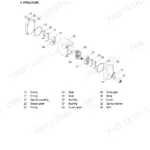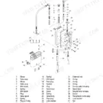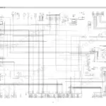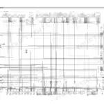


Part of the Hyundai Repair Manuals.
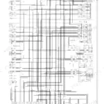
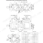
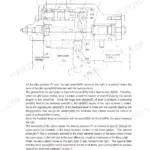
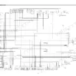
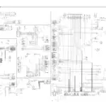
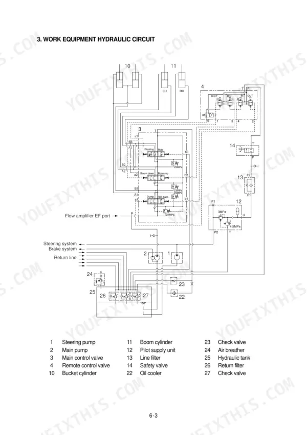
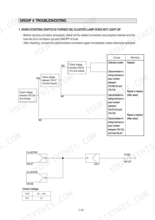
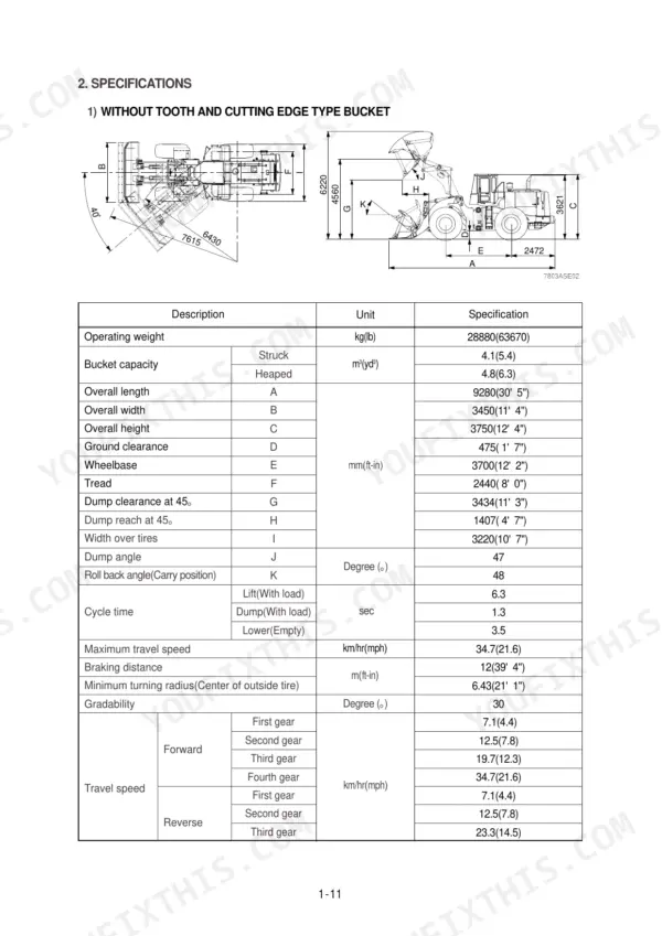
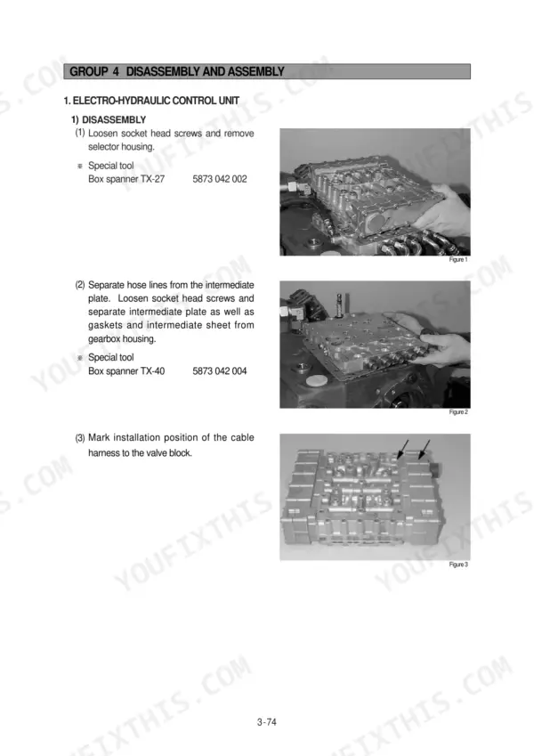
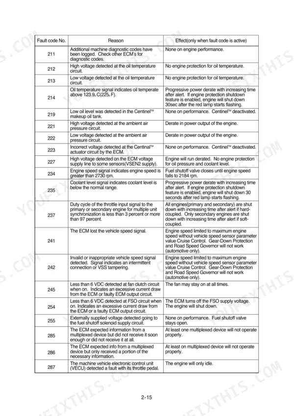
All 635 pages of this Hyundai HL780-3A Service Manual PDF cover one machine family: your wheel loader, from torque converter to bucket pins. You get full electrical circuit diagrams with connector pinouts and component locations, hydraulic schematics tracing the main pump and control valve circuits, and fault code tables for the electro-hydraulic shift control. Inside: step-by-step disassembly and assembly for the multi-disk clutch packs, differential carrier, and steering system, plus rolling resistance adjustment and contact pattern inspection for the axles. Set the main relief valve at 210 kgf/cm2, and torque the rubber engine mounting nuts to 100 plus or minus 15.0 kgf-m before startup. No more chasing wiring faults with a multimeter and a prayer. Bookmarked chapters, text you can search by spec or fault code, and it opens on any device you carry into the shop.
What's Inside This Manual
| System | Pages | Key Topics |
|---|---|---|
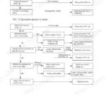
| General | 11-35 | Safety Hints, Specifications, Operational Checkout Record Sheet |
| Engine | 36-54 | Structure and Function, Engine Fault Code Information |
| Power Train System Overview | 55-60 | Component Overview, Torque Converter, Transmission Layout |
| Transmission Operation | 61-73 | Installation View, Forward/Reverse Gear Operation, Electro-Hydraulic Shift Control, Transmission Error Display, Aeb Mode |
| Operating Modes and Fault Codes | 74-125 | Operating Mode Definitions, Fault Code Tables, Differential/Axle Troubleshooting, Drive Line Troubleshooting |
| Tests and Adjustments | 126-152 | Clutch Cut-Off Pressure Switch Test, Transmission Measuring Points, Retarder Disassembly/Assembly |
| Transmission Disassembly and Assembly | 153-261 | Transmission Disassembly, Multi-Disk Clutch Disassembly/Assembly, Input Shaft Assembly, Speed Sensor Installation |
| Axle and Differential Maintenance | 262-338 | Final Drive Disassembly, Differential Carrier Disassembly, Differential Assembly, Rolling Resistance Adjustment, Contact Pattern Inspection |
| Brake System | 339-371 | Structure and Function, Operational Checks and Troubleshooting, Tests and Adjustments |
| Steering System | 372-478 | Structure and Function, Operational Checks and Troubleshooting, Tests and Adjustments, Disassembly and Assembly |
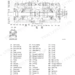
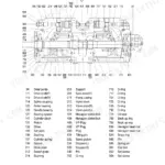
| Work Equipment | 479-558 | Hydraulic System Outline, Hydraulic Circuit, Main Pump Operation, Remote Control Valve, Main Control Valve |
| Electrical System | 559-635 | Component Location, Electrical Circuit, Monitoring System, Electrical Component Specification, Connectors, Troubleshooting |
Quick Reference Specifications
| Specification | Value | Page |
|---|---|---|
| Engine mounting bolt, nut(Rubber, 4EA) | 100 ± 15.0 kgf·m | p. 29 |
| Engine mounling bolt(Fly wheel housing, 8EA) | 19.4 ± 3.0 kgf·m | p. 29 |
| Main pump maximum operating pressure | 210 kgf/cm² | p. 27 |
| Brake pump maximum operating pressure | 150 kgf/cm² | p. 27 |
| Main relief valve pressure | 210 kgf/cm² | p. 27 |
| Overload relief valve pressure(Boom) | 250 kgf/cm² | p. 27 |
| Steering pump maximum operating pressure | 210 kgf/cm² | p. 27 |
| Nominal value/Bearing rolling moment | 1.4~2.0kgf m | p. 269 |
| Slotted nut torque limit | 204~224kgf m | p. 269 |
| Maximum steering pressure | 21 MPa | p. 376 |
| Bypass valve set pressure | 1.36kg/cm2 (19.3psi) | p. 510 |
| Proximity switch clearance | 3±1mm | p. 525 |