


Part of the Hyundai Repair Manuals.
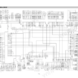
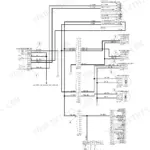
Looking for the Hyundai R140W-7 service manual PDF? You just found all 638 pages of factory workshop coverage for the R140W-7 wheeled excavator, straight from Hyundai. Inside: full electrical wiring circuits, hydraulic schematics with main and pilot circuit routing, self-diagnostic error codes for the mechatronics system, and step-by-step disassembly and assembly for the main pump, swing motor, travel motor, transmission, and steering valve. You also get operational performance tests plus tightening torque charts for every bolt on the machine. Set the pilot relief valve at 40 kgf/cm2, and check solenoid valve resistance at 15 to 25 ohms before you condemn a coil. Chasing an electrical fault through a harness with no diagram is a wasted afternoon. This PDF is bookmarked by section and text-searchable; pull it up on your tablet, walk to the machine, and start wrenching.
What's Inside This Hyundai R140W-7 Manual
| System | Pages | Key Topics |
|---|---|---|
| General | 1-38 | Safety Hints, Specifications |
| Structure and Function | 39-120 | Pump Device, Main Control Valve, Swing Device, Travel Device, Rcv Lever, Accelerator Pedal, Brake Pedal, Transmission |
| Hydraulic System | 121-153 | Main Circuit, Pilot Circuit, Combined Operation |
| Electrical System | 154-205 | Component Location, Electrical Circuit, Electrical Component Specification |
| Mechatronics System | 206-244 | Mode Selection System, Automatic Deceleration System, Engine Control System |
| Maintenance Standard | 303-331 | Operational Performance Test, Major Components, Track and Work Equipment |
| Precautions and Tightening Torque | 332-338 | Removal Work, Installation Work, Completing Work, Tightening Torque Chart |
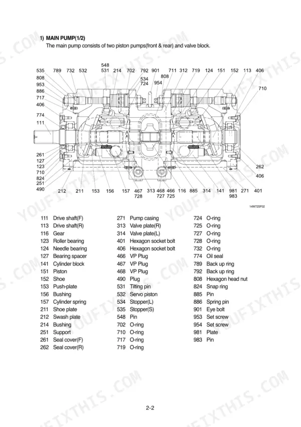
| Pump Device | 339-361 | Removal and Install, Main Pump Structure, Regulator Structure, Disassembly and Assembly, Inspection |
| Main Control Valve | 362-375 | Removal and Install, Main Control Valve Structure, Disassembly and Assembly, Inspection, Relief Valve |
| Swing Device | 376-390 | Removal and Install, Swing Motor Structure, Disassembly and Assembly, Inspection, Brake Assembly |
| Reduction Gear | 391-400 | Removal and Install, Reduction Gear Structure, Disassembly and Assembly |
| Travel Motor | 401-440 | Motor Unit Structure, Control Unit Structure, Counter-Balance Valve, Disassembly and Assembly, Inspection |
| Steering Valve and Final Drive | 441-478 | Final Drive Disassembly, Steering Valve Structure, Steering Valve Disassembly and Assembly, Steering Cylinder |
| Cylinders and Work Equipment | 479-622 | Turning Joint, Boom Cylinder, Arm Cylinder, Bucket Cylinder, Dozer Cylinder, Outrigger Cylinder, Bucket Assembly |
| Component Mounting Torque | 623-638 | Introduction Guide, Engine System, Electric System, Power Train System, Structure, Work Equipment |
Quick Reference Specifications
| Specification | Value | Page |
|---|---|---|
| Bypass check valve (1) setting pressure | 5.0kgf/cm2 (71psi) | p. 124 |
| Bypass check valve (2) setting pressure | 3.0kgf/cm2 (43psi) | p. 124 |
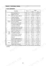
| Solenoid valve resistance | 15~25 ohm | p. 177 |
| Transducer (Pump 1,2) 0bar voltage | 1V | p. 182 |
| Transducer (Pump 1,2) 500bar voltage | 5V | p. 182 |
| Engine Rated Horsepower | 115 Hp | p. 34 |
| Main Pump Maximum Pressure | 330 kgf/cm2 | p. 34 |
| Swing Motor Relief Pressure | 240 kgf/cm2 | p. 35 |
| Travel Motor Relief Pressure | 360 kgf/cm2 | p. 35 |
| Engine Oil Capacity | 15.3 L | p. 34 |
| Hydraulic Tank Capacity | 124 L | p. 38 |
| Fuel Tank Capacity | 270 L | p. 38 |
Hyundai R140W-7 Common Problems This Manual Covers
Hyundai R140W-7 hydraulic functions slow and weak, pump whines like it's cavitating under load
Check hydraulic oil level first; the tank holds 124 L and a low fill starves the pump. Pull and clean the suction strainer, then clean the reservoir breather. If action stays weak, test main relief pressure against the 330±10 kgf/cm2 spec on page 321 before condemning the pump.
Manual Section: Hydraulic and Mechanical System TroubleshootingSwing won't start, drifts past the stop, or upper structure creeps on a slope
Verify swing relief pressure against the 240 kgf/cm2 spec on page 321; a stuck or mis-set relief lets the upper structure drift. Inspect the swing brake release valve for sticking. If you reseat or replace the relief cartridge, torque the relief assembly to 8 kgf·m (58 lbf·ft) per page 389.
Manual Section: Swing Device TroubleshootingTravel weak or dead on one side, machine pulls hard to one direction
Test travel relief pressure on the weak side; normal spec is 330±10 kgf/cm2 per page 321. Swap the relief cartridges side to side, and if the fault follows the cartridge, replace it. If pressures check good, inspect the travel control valve spool for sticking and check the counter-balance valve, covered starting on page 401.
Manual Section: Travel System TroubleshootingEngine runs fine but boom, arm, and bucket barely move or won't respond
Check pilot pressure first; the pilot relief valve sets at 40 kgf/cm2, detailed on page 126. Low pilot pressure keeps every spool from stroking. Verify the safety lever position, then test the safety solenoid valve coil; resistance should read 15 to 25 ohms per page 177. Replace the solenoid if it reads open or shorted.
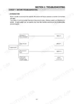
Manual Section: Hydraulic and Mechanical System TroubleshootingAll functions slow in every work mode, engine bogs down when pump loads up
Measure engine speed with no load; H-mode should hold 2200±50 rpm, listed on page 286. If speed checks good, test the EPPR valve: coil resistance should read 17.5±1 ohms per page 287, and output pressure should fall between 5 and 20 kgf/cm2 per page 288. Replace the valve if either value is out.
Manual Section: Mechatronics System Troubleshooting p. 286Frequently Asked Questions
How do I clear fault codes on a Hyundai R140W-7?
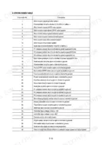
To delete all recorded error codes, select the recorded error (TIME Er) display on the cluster. Then, press the engine switch and the select switch at the same time for 2 seconds or more. The cluster display will change to 'TIME Er : 00', indicating that the CPU controller has deleted all recorded error codes from the memory. p. 218
What is the torque specification for the engine mounting bolts on the Hyundai R140W-7?
The engine mounting bolts and nuts (M20 x 2.5) on the Hyundai R140W-7 should be tightened to a torque of 55 ± 3.5 kgf·m (398 ± 25.3 lbf·ft). p. 336
What is the procedure for bleeding air from the hydraulic pump after installation?
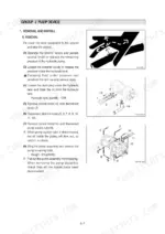
After installing the pump, remove the air vent plug (2EA) and tighten it lightly. Start the engine and run it at low idling until oil comes out from the plug, then tighten the plug fully. p. 340
What is the standard torque for the main pump mounting bolts?
The main pump mounting bolts (M16 x 2.0) should be tightened to a torque of 22.1 ± 2.4 kgf·m (159 ± 17.3 lbf·ft). p. 336
What is the recommended oil for the engine oil pan at an ambient temperature of 20°C?
At an ambient temperature of 20°C, the recommended engine oil for the engine oil pan is SAE 10W-30 or SAE 15W-40. p. 38
What exactly do I receive with this Hyundai R140W-7 Service Manual?
You download the Service Manual yourself: 638 pages, searchable PDF, available immediately. Keep a copy on every device you use.
Can I print pages of this Hyundai R140W-7 manual for my own shop?
Yes. Print the pages you need for the job in your own shop, and bin them when they get greasy.








Reviews
There are no reviews yet.