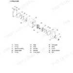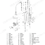


Part of the Hyundai Repair Manuals.
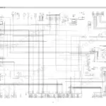
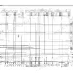
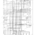
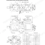
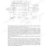
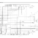
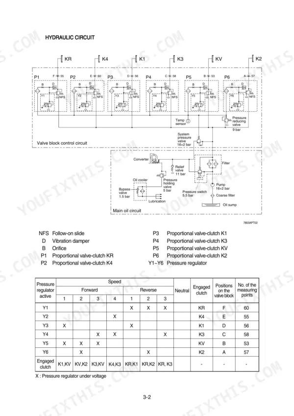
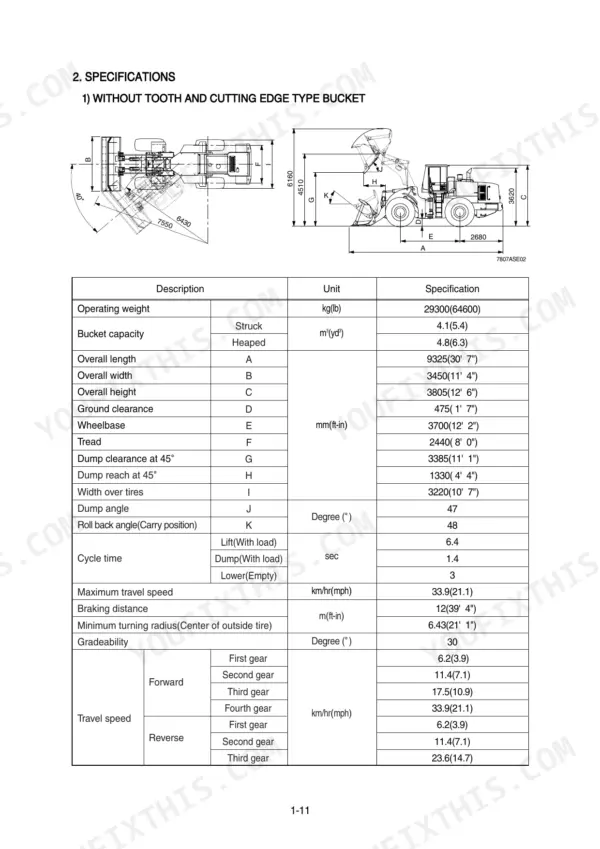
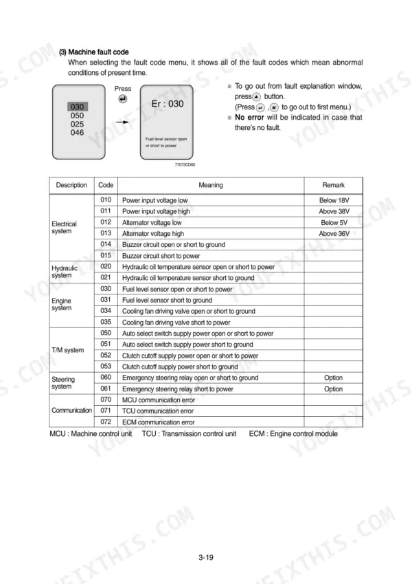
Need the factory answers for your Hyundai HL780-7A wheel loader? This 584-page Hyundai HL780-7A service manual PDF breaks down the whole machine: torque converter and transmission, axles and differentials, brakes, steering, work equipment, and the full electrical system. Inside you get complete wiring circuits with connector specs, hydraulic schematics with fluid routing, transmission fault codes paired with troubleshooting charts, and long step-by-step disassembly and assembly procedures for every major system. Operational checkout sheets and tests-and-adjustments sections round it out. Set the main relief valve to 210 kgf/cm2 (2987 psi) and the boom overload relief to 240 kgf/cm2 (3414 psi), straight from the spec tables. No more chasing shift faults with a multimeter and a prayer. Bookmarked with a real text layer: search any spec, jump to any circuit, get the loader back to work.
What's Inside This Manual
| System | Pages | Key Topics |
|---|---|---|
| General | 1-8 | Safety Hints, Specifications, Operational Checkout Record Sheet |
| Engine | 9-36 | Safety Hints, Specifications |
| Power Train System Overview and Torque Converter | 37-41 | Component Overview, Torque Converter, Hydrodynamic Torque Converter Function |
| Transmission Layout and Operation | 42-50 | Transmission Layout, Installation View, Forward Gear Operation, Reverse Gear Operation |
| Electro-Hydraulic Shift Control and Monitoring | 51-65 | Electro-Hydraulic Shift Control, Gear Selector, LCD Monitoring, Fault Codes, Operating Modes |
| Transmission Troubleshooting and Fault Codes | 66-113 | Transmission Fault Codes, Troubleshooting Charts, Transmission Pressure, Transmission Shifts |
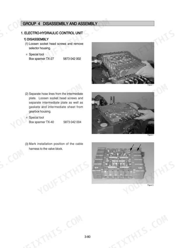
| Transmission Disassembly and Assembly | 114-166 | Electro-Hydraulic Control Unit, Retarder, Transmission Disassembly, Multi-Disk Clutch Assembly |
| Axle and Differential Components | 167-288 | Axle Operation, Limited Slip Differential, Final Drive, Differential Carrier, Drive Unit |
| Brake System | 289-319 | Structure and Function, Operational Checks and Troubleshooting, Tests and Adjustments |
| Steering System | 320-423 | Structure and Function, Operational Checks and Troubleshooting, Tests and Adjustments, Disassembly and Assembly |
| Work Equipment | 424-505 | Structure and Function, Operational Checks and Troubleshooting, Tests and Adjustments, Disassembly and Assembly |
| Electrical System | 506-584 | Component Location, Electrical Circuit, Monitoring System, Electrical Component Specification, Connectors, Troubleshooting |
Quick Reference Specifications
| Specification | Value | Page |
|---|---|---|
| Main relief valve pressure | 210kgf/cm2 (2987psi) | p. 27 |
| Overload relief valve pressure(Boom) | 240kgf/cm2 (3414psi) | p. 27 |
| Main pump maximum operating pressure | 210kgf/cm2 (2987psi) | p. 27 |
| Brake pump maximum operating pressure | 150kgf/cm2 (2130psi) | p. 27 |
| Clutch cut-off pressure switch rated pressure | 25kgf/cm2 | p. 114 |
| Dimension b (gap between measuring pin and measuring shaft) | 0.70mm | p. 275 |
| Dimension a (measuring piston) | 166.80mm | p. 275 |
| Clutch cut-off adjusting range | 20 ~ 50 kgf/cm2 | p. 306 |
| Hydraulic oil tank capacity | 210 L (55.5 U.S. gal) | p. 349 |
| Orifice in LS-connection hexagon key size | 6mm | p. 368 |
| Throttle check valve in PP-connection hexagon key size | 6mm | p. 368 |
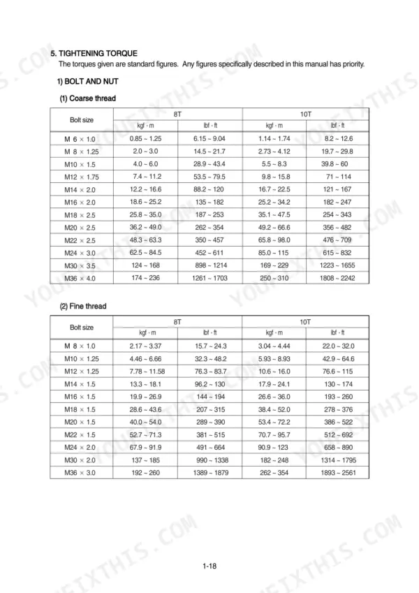
| Pressure relief valve tightening torque | 3.1 ± 0.3 kgf·m (22.4 ± 2.2 lbf·ft) | p. 384 |