
Part of the Hyundai Repair Manuals.
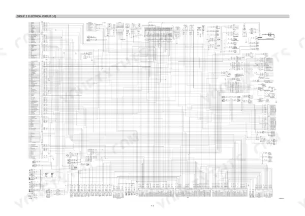
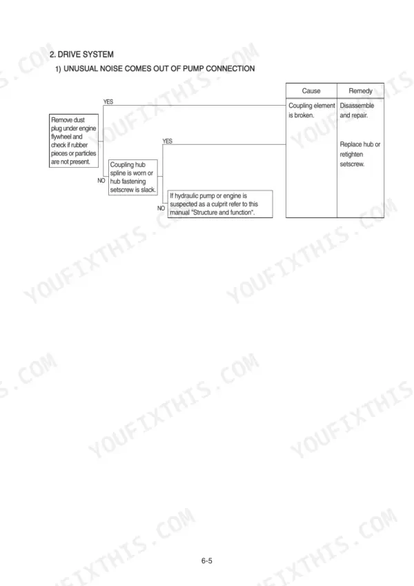
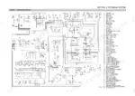
Wrenching on a Hyundai R210W-9? This 684-page Hyundai R210W-9 shop manual PDF covers the wheeled excavator front to back, from main pump and control valve through swing device, travel motor, transmission, and both axles. You get full hydraulic circuit schematics with main and pilot routing, factory wiring diagrams with connector pinouts, and a fat troubleshooting section spanning hydraulic, electrical, and mechatronics faults, including the self-diagnostic system. Step-by-step disassembly and assembly runs clear through the steering valve, RCV lever, turning joint, and every cylinder on the machine. Set the arm cylinder M12x1.75 bolts to 5.5 kgf-m and confirm the bypass relief valve cracks open at 1.5 kgf/cm2 before you button it up. Downtime on a wheeled machine bleeds money fast. Bookmarked and keyword-searchable; jump straight to the spec and get back in the seat.
What's Inside This Hyundai R210W-9 Manual
| System | Pages | Key Topics |
|---|---|---|
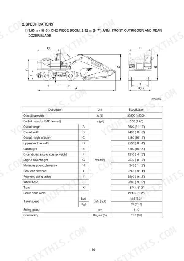
| General | 12-38 | Safety Hints, Specifications |
| Structure and Function | 39-131 | Pump Device, Main Control Valve, Swing Device, Travel Motor, Rcv Lever, Accelerator Pedal, Brake Pedal, Transmission |
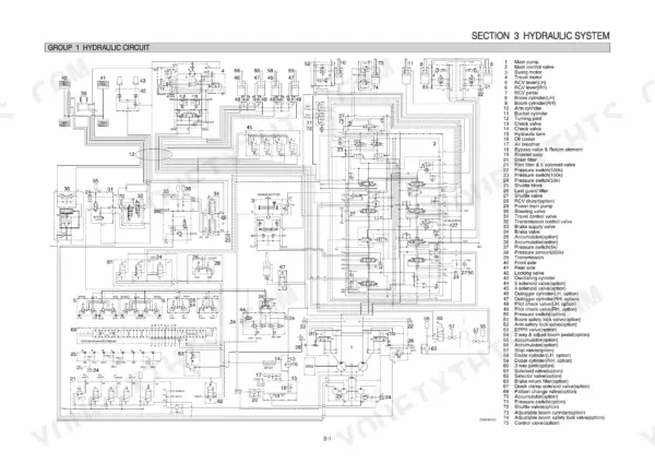
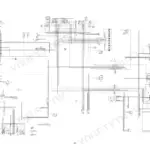
| Hydraulic System | 132-164 | Hydraulic Circuit, Main Circuit, Pilot Circuit |
| Electrical System | 165-220 | Component Location, Electrical Circuit, Electrical Component Specification |
| Mechatronics System | 221-254 | Outline, Mode Selection System, Automatic Deceleration System |
| Maintenance Standard | 336-364 | Operational Performance Test, Major Components, Track and Work Equipment |
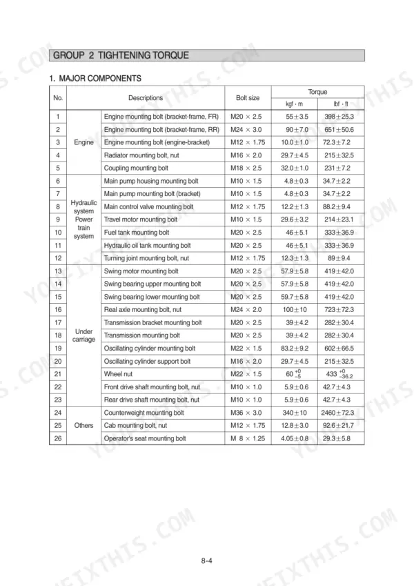
| General Precautions and Tightening Torque | 365-371 | Removal Work, Install Work, Tightening Torque, Pipe and Hose Fittings |
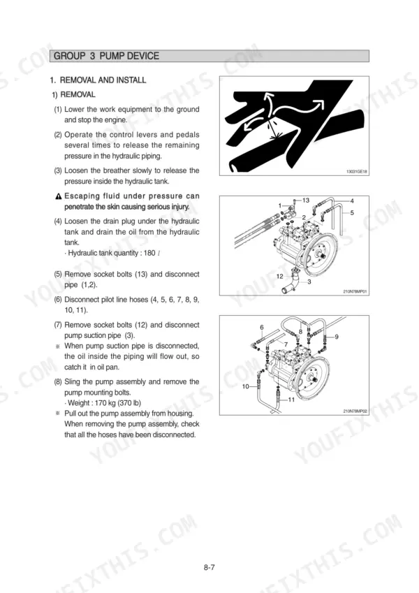
| Pump Device | 372-416 | Removal and Install, Main Pump Structure, Disassembly and Assembly, Reduction Gear |
| Transmission | 417-450 | Reduction Gear Structure, Disassembly and Assembly, Output Disassembly, Tightening Torque |
| Steering Valve | 451-528 | General Instructions, Labour Safety, Lubricant Specifications, Disassembly and Assembly, Tools |
| Front Axle | 529-584 | Removal and Install, Differential Section, Final Drive, Brake Wear Measurement |
| Rear Axle | 585-623 | Removal and Install, Differential Disassembly, Output Disassembly, Oil Drain and Filler Plugs |
| Rcv Lever and Turning Joint | 624-643 | Rcv Lever Removal and Install, Rcv Lever Disassembly, Turning Joint Removal and Install, Turning Joint Disassembly |
| Boom, Arm, Bucket, Dozer and Outrigger Cylinders | 644-668 | Bucket Cylinder, Arm Cylinder, Boom Cylinder, Dozer Cylinder, Outrigger Cylinder |
| Component Mounting Torque | 669-684 | Introduction Guide, Engine System, Electric System, Power Train System, Structure, Work Equipment |
Quick Reference Specifications
| Specification | Value | Page |
|---|---|---|
| Battery | 2 x 12 V x 100 Ah | p. 34 |
| bypass relief valve opening pressure | 1.5 kgf/cm2 | p. 135 |
| Battery relay | 24V 100A | p. 190 |
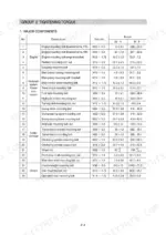
| Boom cylinder (M10x1.5) | 3.2 ± 0.3 kgf·m | p. 677 |
| Arm cylinder (M12x1.75) | 5.5 ± 0.6 kgf·m | p. 677 |
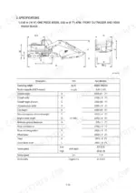
| Operating weight | 20500 kg | p. 22 |
| Travel speed (High) | 35 km/hr | p. 22 |
| Swing speed | 11.0 rpm | p. 22 |
| Engine oil quantity | 24 L | p. 34 |
| Main pump maximum pressure | 330 kgf/cm2 | p. 34 |
| Swing motor relief pressure | 265 kgf/cm2 | p. 35 |
| Travel motor rated pressure | 380 kgf/cm2 | p. 35 |
Hyundai R210W-9 Common Problems This Manual Covers
Hyundai R210W-9 boom lifts slowly and loses power under load, cylinders drift under a full bucket
Check hydraulic oil level and condition first; milky or dark oil means water or wear metal contamination. Test main pump output against the 330 kgf/cm2 maximum pressure spec on page 34. Replace the return filter if the bypass relief opens past its 1.5 kgf/cm2 setting shown on page 135, then work through the procedure.
Manual Section: Hydraulic and Mechanical System Troubleshooting p. 34Machine pulls to one side during travel, travel action powerless climbing grades
Test travel circuit pressure on both sides against the 380 kgf/cm2 travel motor rated pressure listed on page 35. One side reading low points to a worn travel motor or leaking counterbalance valve. Follow the travel troubleshooting steps starting, and check for brake drag at the wheel on the affected side.
Manual Section: Hydraulic and Mechanical System Troubleshooting p. 35Engine rpm won't climb past 1300 when travel pedal is pressed, machine only crawls
Check the travel forward and reverse pressure sensor circuits before condemning the engine; the controller holds rpm down when it sees a bad pump load signal. Measure EPPR valve current draw against the electrical component specification in the Electrical System section, then pull stored faults using the code reference on page 236.
Manual Section: Mechatronics System Troubleshooting p. 236Monitor panel flickers and controller acts up intermittently after electrical or battery work
Verify battery voltage before chasing controller faults; the machine runs two 12V 100Ah batteries in series per page 34, so anything under 24V loaded is suspect. Test the battery relay, rated 24V 100A on page 190, clean its ground connections, and trace intermittent circuits with the wiring diagram.
Manual Section: Electrical System Troubleshooting p. 190Boom cylinder weeps oil at the rod seal and boom drifts down overnight
Inspect the rod for scoring and pitting before ordering seals; a damaged rod chews up new seals within days. Rebuild the cylinder following the procedure starting on page 644, checking the cylinder bore against the specification table in the General section for wear, and torque the M10x1.5 fasteners to 3.2 kgf·m per page 677.
Manual Section: Boom, Arm, Bucket, Dozer and Outrigger Cylinders p. 644Frequently Asked Questions
What does the communication fault code 840 mean on the Hyundai R210W-9?
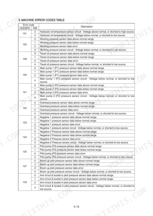
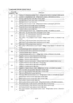
The communication error code 840 indicates a failure in the serial communication between the MCU and the cluster. To troubleshoot, check the connection between CN-51(33) and CN-56(4) or CN-51(23) and CN-56(8) as detailed on page 281. p. 281
How do I clear fault codes on the Hyundai R210W-9?
You can clear logged faults of the MCU or engine ECM using the 'Delete fault' menu on the cluster. Navigate to the 'Monitoring' menu, select 'Logged Fault', and then choose 'Delete Logged Fault' to clear all stored fault codes. p. 235
What is the tightening torque for the engine mounting bolts on the R210W-9?
The tightening torque for the engine mounting bolts (bracket-frame, FR) is 55 ± 3.5 kgf·m (398 ± 25.3 lbf·ft). p. 369
What is the hydraulic tank capacity for the R210W-9?
The hydraulic tank capacity is 165 liters (43.6 U.S. gal), with a total system capacity of 340 liters (89.8 U.S. gal). p. 38
What is the standard tightening torque for the M12 socket head bolts on the main control valve?
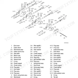
The standard tightening torque for M12 socket head bolts on the main control valve is 12.2 ± 1.3 kgf·m (88.2 ± 9.4 lbf·ft). p. 369
Will this Hyundai R210W-9 Shop Manual download right away?
Instant PDF download. You get the full 684-page searchable Shop Manual immediately after payment. Open it on your laptop, tablet, or phone right in the shop.
Does this Hyundai R210W-9 manual allow printing?
Yes. Print the sections you need to take out to the shop for your own use. Standard letter or A4 paper works.








Reviews
There are no reviews yet.