

Part of the Hyundai Repair Manuals.
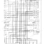
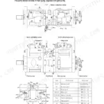
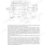
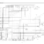
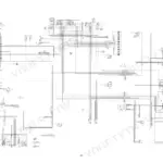
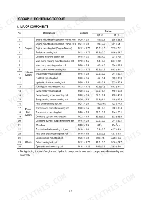
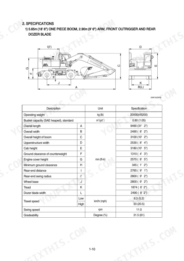
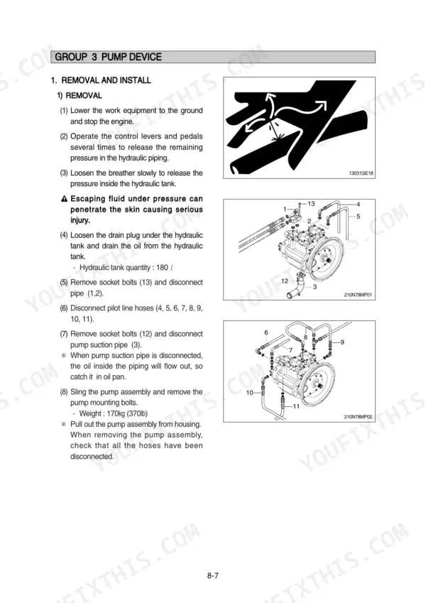
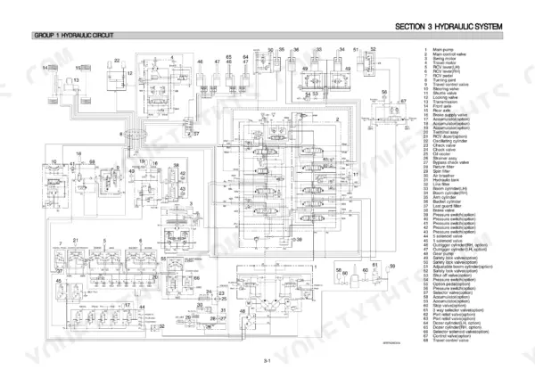
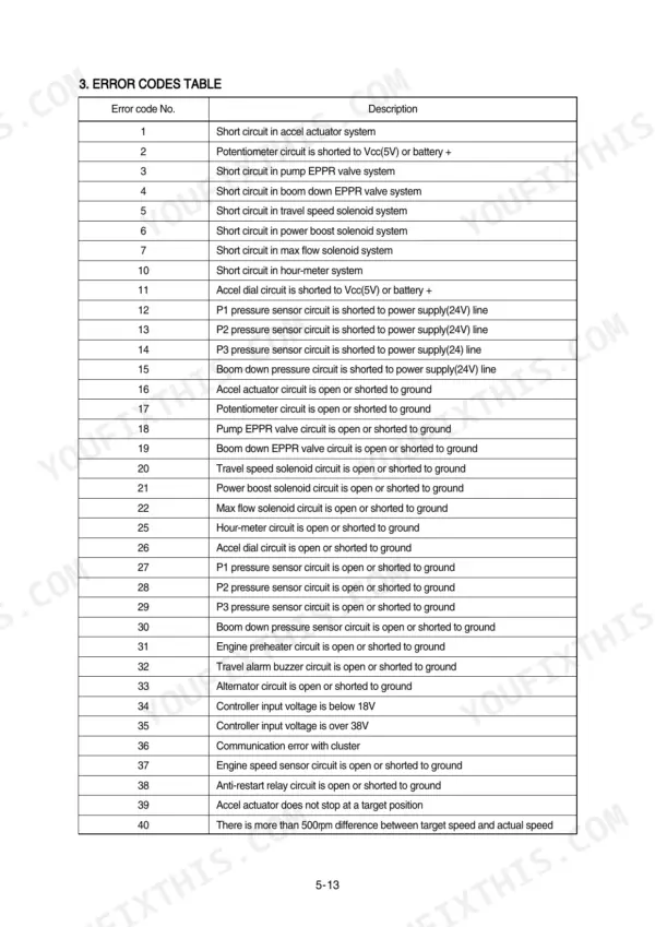
Looking for the Hyundai R200W-7A shop manual PDF? All 666 pages of this factory shop manual cover the R200W-7A hydraulic excavator from pump device to rear axle. You get full hydraulic schematics tracing the main and pilot circuits, wiring diagrams with component locations and connector views, self-diagnostic error codes for the mechatronics system, and step-by-step disassembly procedures for the main pump, control valve, travel motor, transmission, steering valve, and both axles. Torque the swing bearing mounting bolts, upper and lower, to 57.8 kgf·m, and confirm the bypass relief valve opens at 1.5 kgf/cm2. No more chasing faults in your excavator's harness with a multimeter and a prayer. Bookmarked PDF with a full text layer: search any spec, jump straight to the right section, and get back on the machine.
What's Inside This Manual
| System | Pages | Key Topics |
|---|---|---|
| General | 12-38 | Safety Hints, Specifications |
| Structure and Function | 39-134 | Pump Device, Main Control Valve, Swing Device, Travel Device, Rcv Lever, Accelerator Pedal, Brake Pedal, Transmission |
| Hydraulic System | 135-168 | Hydraulic Circuit, Main Circuit, Pilot Circuit |
| Electrical System | 169-223 | Component Location, Electrical Circuit, Electrical Component Specification |
| Mechatronics System | 224-264 | Outline, Mode Selection System |
| Maintenance Standard | 313-341 | Operational Performance Test, Major Components, Track and Work Equipment |
| General Precautions and Tightening Torque | 342-348 | Safety Precautions, Tightening Torque Charts, Pipe and Hose Specifications, Fitting Specifications |
| Pump Device Disassembly and Assembly | 349-377 | Main Pump Removal, Main Pump Installation, Regulator Disassembly, Regulator Assembly, Gear Pump |
| Main Control Valve Disassembly and Assembly | 378-405 | Main Control Valve Removal, Main Control Valve Installation, Spool Valve Disassembly, Relief Valve Maintenance, Port Relief Valve |
| Travel Motor Disassembly and Assembly | 406-483 | Travel Motor Removal, Travel Motor Installation, Counter-Balance Valve, Downshift Interlock, Drive Shaft Sealing |
| Steering Valve Disassembly and Assembly | 484-508 | Steering Valve Removal, Steering Valve Installation, Steering Valve Disassembly, Dual Shock Valve, Steering Angle Setting |
| Front and Rear Axle Disassembly and Assembly | 509-603 | Front Axle Removal, Rear Axle Removal, Differential Disassembly, Input Flange, Hub Carrier |
| Rcv Lever Disassembly and Assembly | 604-625 | Rcv Lever Removal, Rcv Lever Installation, Pilot Valve Disassembly, Pilot Valve Assembly, Turning Joint |
| Work Equipment Disassembly and Assembly | 626-650 | Bucket Cylinder Removal, Arm Cylinder Removal, Boom Cylinder Removal, Dozer Cylinder Removal, Outrigger Cylinder Removal |
| Component Mounting Torque | 651-666 | Introduction Guide, Engine System, Electric System, Power Train System, Structure, Work Equipment |
Quick Reference Specifications
| Specification | Value | Page |
|---|---|---|
| Bypass relief valve opening pressure | 1.5kgf/cm2 | p. 138 |
| Spin filter drain oil pressure | 1.5kgf/cm2 | p. 139 |
| Main relief valve, port relief valve & negative control relief valve - Replacement | 100% replacement in general | p. 333 |
| Swing bearing upper mounting bolt | 57.8 ± 6.4 kgf·m | p. 347 |
| Swing bearing lower mounting bolt | 57.8 ± 6.4 kgf·m | p. 347 |
| Main relief valve tightening torque | 7~8 kgf·m (50.6~57.8 lbf·ft) | p. 389 |
| Engine oil quantity | 24 L | p. 34 |
| Battery | 2 x 12V x 100Ah | p. 34 |
| Main pump rated oil flow | 2 x 222 L/min | p. 34 |
| Main relief valve pressure | 330 kgf/cm2 | p. 35 |
| Swing motor braking torque | 59 kgf m | p. 35 |
| Transmission weight | 140 kg | p. 124 |