
![Hyundai HSL800T Repair Manual [Skid Steer Loader]](https://youfixthis.com/wp-content/uploads/2016/02/2016-02-16_11-07-01-1-300x300.jpg)

Part of the Hyundai Repair Manuals.
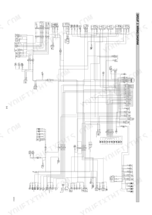
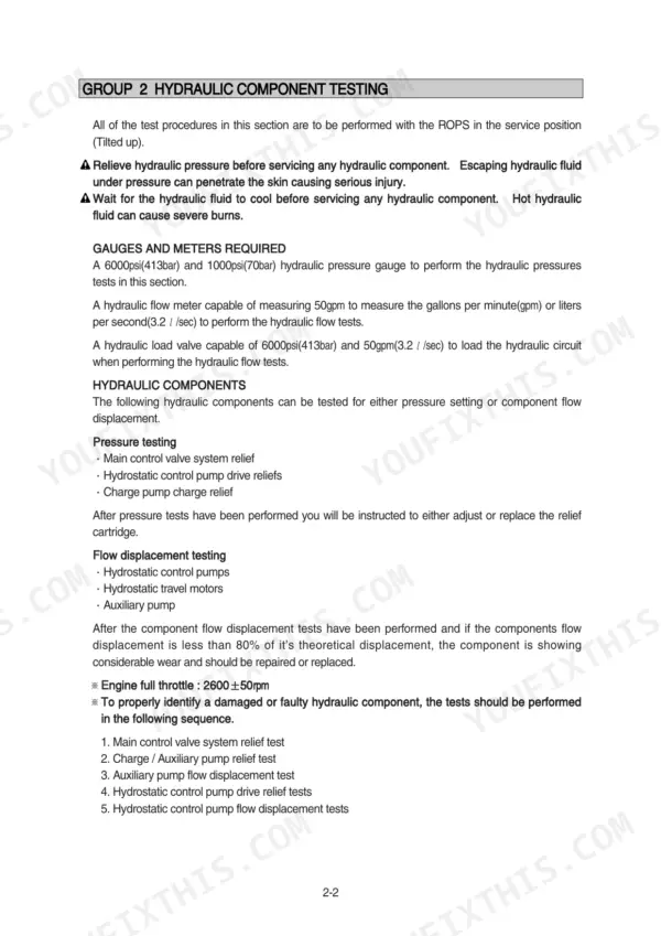
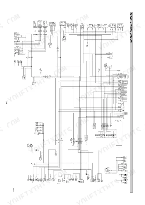
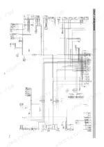
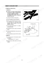
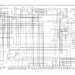
Every one of the 138 pages in this Hyundai HSL850-7 Repair Manual PDF targets one machine: your HSL850-7 skid steer loader, from the self-level valve to the chain drive. Inside: the complete hydraulic circuit diagram with pressure and flow testing for the main control valve, charge pump, and hydrostatic control pump, plus full wiring diagrams with electrical component locations. You also get teardown and rebuild procedures for the main pump, travel motor, and boom and bucket cylinders, backed by a troubleshooting section covering travel hydraulics, power train, and electrical faults. Set the hydrostatic control pump relief valve at 3915 ± 200 psi (270 bar), and torque SAE size 8 flare fittings to 5.1 to 6.3 kgf·m. A dead loader earns nothing sitting in the yard. This bookmarked PDF has a real text layer; type the spec you need, jump straight to it, and get wrenching.
What's Inside This Hyundai HSL850-7 Repair Manual
| System | Pages | Key Topics |
|---|---|---|
| General | 1-21 | Safety Hints, Specifications, Maintenance |
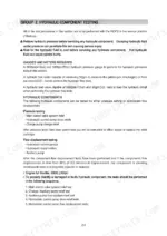
| Hydraulic Circuit and Component Testing | 22-29 | Hydraulic Circuit Diagram, Main Control Valve System Pressure, Auxiliary Pump Flow, Charge Pump Pressure, Hydrostatic Control Pump Pressure, Hydrostatic Control Pump Flow |
| Self Level Valve | 30-35 | Structure, Hydraulic Circuit, Self Leveling Operation, Bucket Cylinder Extension, Retracting Boom Cylinder, Extending Bucket Cylinder, Retracting Bucket Cylinder |
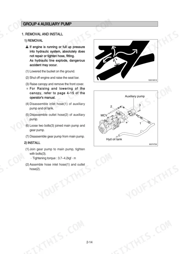
| Auxiliary Pump | 36-45 | Removal and Install, Disassembly, Assembly, Inspection for Wear |
| Main Pump | 46-64 | Removal and Install, Structure, General Description, Transmission Hydraulic Support System, Controls and Options, Start Up and Maintenance, Troubleshooting |
| Travel Motor | 65-83 | Shaft Seal Replacement, Bypass Valve, Charge Check and High Pressure Relief Valves, Integral Charge Pump, Control Spool, Removal and Install, Structure, Disassembly |
| Main Control Valve | 84-91 | Removal and Install, Structure, Boom Spool, Bucket Spool, Auxiliary Spool, Load Check Valve, Main Relief Valve |
| Boom and Bucket Cylinder | 92-96 | Removal and Install, Structure, Disassembly, Assembly |
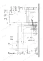
| Electrical System | 97-116 | Component Location, Wiring Diagram |
| Power Train | 117-122 | Front Axle Shaft, Rear Axle Shaft, Front Sprocket, Rear Sprocket, Chain Assembly, Taper Roller Bearing |
| Control | 123-129 | Hand Control, Parking Brake, Attachment Holder, Quick Coupler |
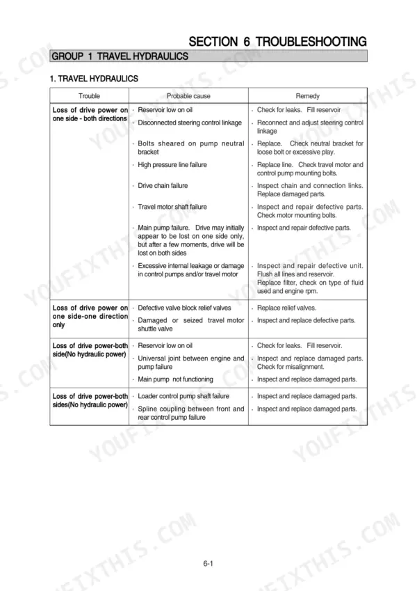
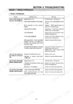
| Troubleshooting | 130-138 | Travel Hydraulics, Boom and Bucket Hydraulic, Power Train, Control, Electrical System |
Quick Reference Specifications
| Specification | Value | Page |
|---|---|---|
| Torque for SAE size 4 flare type fitting | 1.1 - 1.6 kgf·m | p. 18 |
| Torque for SAE size 6 flare type fitting | 2.6 - 3.1 kgf·m | p. 18 |
| Travel motor capacity | 523.6 cc/rev | p. 14 |
| Main pump capacity | 2 x 46 cc/rev | p. 12 |
| Hydrostatic control pump relief valve pressure | 3915 ± 200psi (270 ± 14bar) | p. 28 |
| Charge relief pressure | 300psi (20bar) minimum | p. 27 |
| Auxiliary pump flow | 20gpm (1.26 l/sec) | p. 26 |
| Tightening torque for gear pump to main pump bolts | 3.7~4.2kgf·m | p. 36 |
| Tighten torque for pump mounting bolts (Nut 2) | 19.6±2.9kgf·m (142±21.0lbf·ft) | p. 46 |
| Engine oil quantity | 13.2 L | p. 15 |
| Main relief valve pressure | 175 kgf/cm2 | p. 14 |
| Hydraulic tank capacity | 56 L | p. 15 |
Hyundai HSL850-7 Common Problems This Manual Covers
Hyundai HSL850-7 loses drive on one side in both directions, opposite side still pulls fine
Check hydraulic reservoir level first; the tank holds 56 L and low oil starves one side before the other. Inspect the steering control linkage for disconnected or misadjusted rods, then look for sheared pump neutral bracket bolts. Work the travel hydraulics chart starting on page 131 before condemning the pump or travel motor.
Manual Section: Travel Hydraulics Troubleshooting p. 131One side quits first, then both sides lose drive after a few seconds of operation
Drain a fluid sample and check for contamination or the wrong oil, then replace the hydraulic filters before anything else. Test charge pressure next; page 27 gives the procedure, and you need 300 psi (20 bar) minimum. If charge pressure falls off as the oil warms up, suspect internal leakage in the control pumps or travel motor.
Manual Section: Hydraulic Circuit and Component Testing p. 27No drive on one side in forward only, works fine in reverse
Test the hydrostatic control pump relief valves using the procedure on page 28; the reading should be 3915 ± 200 psi (270 ± 14 bar). If one reads low, swap the valves side to side and see if the problem follows. A seized travel motor or stuck shuttle valve shows the same symptom, so check those before buying parts.
Manual Section: Hydraulic Circuit and Component Testing p. 28Boom raises slow and jerky under load, bucket leaks down when parked overnight
Verify main relief valve pressure against the 175 kgf/cm2 spec on page 14 before tearing into cylinders. If pressure checks out, pull the boom cylinders and inspect the piston seals; a worn seal lets the boom drift with the engine off. Torque the boom cylinder to 68 kgf·m on reassembly.
Manual Section: Boom and Bucket Hydraulic TroubleshootingGrinding noise from the final drive and chain case rattle when traveling at full speed
Remove the chain case cover and check drive chain tension and sprocket tooth wear on both sides. Inspect the axle taper roller bearings for play; the power train section starting on page 117 covers axle shaft and sprocket service. Torque the axle nut to 76 lbf·ft (103 Nm) when you button it back up.
Manual Section: Power Train p. 117Frequently Asked Questions
What is the torque specification for the main pump mounting bolts on the HSL850-7?
The main pump mounting bolts (Bolt 3) must be tightened to a torque of 6.9 ± 1.4 kgf·m (49.9 ± 10.1 lbf·ft). p. 46
What are the replacement specifications for hydraulic hoses and tubes?
Replace hoses and tubes if they are crushed, dented, or leaking at the coupling areas. Additionally, replace them if the surface is damaged or abraded, if there is rust in the auxiliary wire, if the hose is swelled up, or if it is twisted, crushed, loose, or transformed. p. 16
What is the engine oil capacity for the Kubota V3300DI engine?
The engine oil quantity for the Kubota V3300DI engine is 13.2 liters. p. 13
What is the recommended service interval for changing the hydraulic fluid and filter?
It is recommended that the hydraulic fluid and filter be changed every 500 hours of operation. p. 57
What is the main relief valve pressure for the main control valve?
The main relief valve pressure for the main control valve is 175 kgf/cm² (2490 psi). p. 14
How will I receive this Hyundai HSL850-7 Repair Manual?
Immediate download of the complete 138-page searchable Repair Manual. Access it on any device, from a laptop at your desk to a phone in the field.
Can I print this Hyundai HSL850-7 manual?
Yes. Print individual pages or full chapters for your own shop use, on letter or A4 paper.








Reviews
There are no reviews yet.