
Part of the Hyundai Repair Manuals.
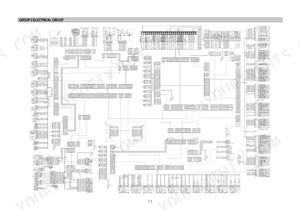
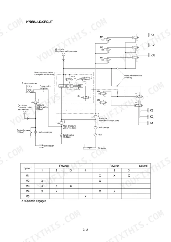
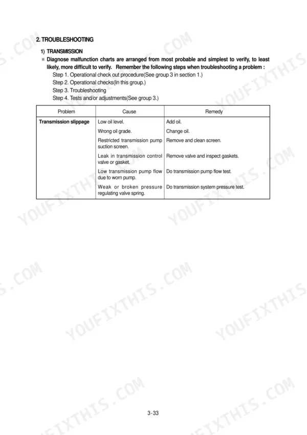
Need factory data for your Hyundai HL720-3? This 470-page Hyundai HL720-3 service manual PDF covers the whole wheel loader, from torque converter to bucket cylinder. Inside: full hydraulic schematics for the brake, steering, and loader circuits, complete wiring diagrams with connector tables, and step-by-step disassembly procedures for the main pump, transmission, and boom cylinders. You also get troubleshooting charts plus factory test procedures, from cylinder drift checks to pilot pressure tests, so you can diagnose before you tear anything down. Set the loader relief valve between 190 and 200 bar, then torque the engine mounting bolts to 12.8 kgf·m. Your loader is down and every idle hour costs money. Get the factory numbers, not forum guesses. This bookmarked PDF opens on any device; search a spec by keyword, walk to the machine, and start wrenching.
What's Inside This Hyundai HL720-3 Manual
| System | Pages | Key Topics |
|---|---|---|
| Conversion Table | 3-8 | Method of Using the Conversion Table, Example, Millimeters to Inches, Kilogram to Pound, Liter to U.S. Gallon, Liter to U.K. Gallon, Kg M to Lb Ft, Kg/Cm2 to Lb/In2 |
| General | 9-32 | Safety Hints (Follow Safe Procedure, Wear Protective Clothing, Warn Others of Service Work, Use Handholds and Steps, Prepare for Emergencies, Work in Clean Area, Protect Against Flying Debris, Protect Against Noise, Park Machine Safely, Support Machine Properly, Service Cooling System Safely, Handle Fluids Safely-Avoid Fires, Beware of Exhaust Fumes, Remove Paint Before Welding or Heating, Illuminate Work Area Safely, Service Machine Safely, Stay Clear of Moving Parts, Avoid High Pressure Fluids, Avoid Heating Near Pressurized Fluid Lines, Prevent Battery Explosions, Prevent Acid Burns, Use Tools Properly, Service Tires Safely, Use Proper Lifting Equipment, Dispose of Fluids Properly, Replace Safety Signs, Live with Safety, Keep ROPS Installed Properly) |
| Engine | 33-36 | Structure, Lube Oil Circuit Schematic, Fuel System Schematic, Cooling System Schematic |
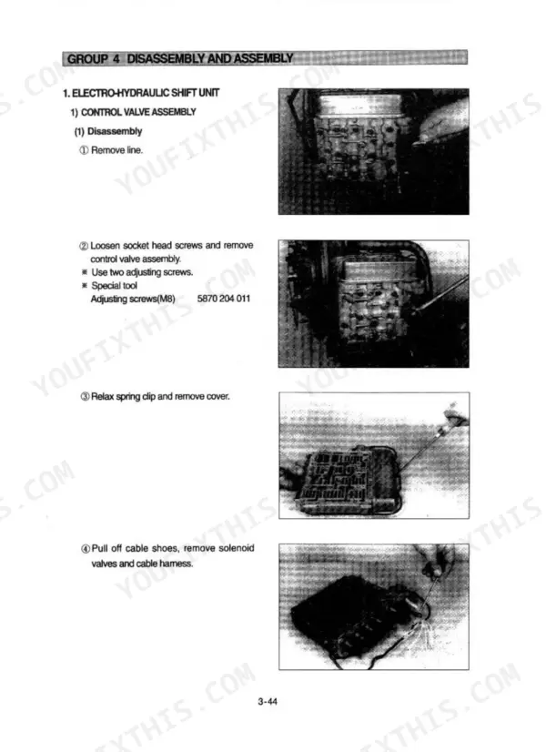
| Power Train System | 37-200 | Structure and Function (Power Train Component Overview, Hydraulic Circuit, Torque Converter, Transmission, Electro-Hydraulic Shift Unit, Speed Control Functional Description, Axle, Differential, Torque Proportioning Differential, Final Drive, Tire and Wheel) |
| Brake System | 201-237 | Structure and Function (Outline, Full Power Hydraulic Brake System, Hydraulic Circuit, Brake Pump, Principle of Operation, Brake Valve, Brake Accumulator, Pressure Switches) |
| Steering System | 238-301 | Structure and Function (Outline, Hydraulic Circuit, Priority Valve, Steering Unit, Steering Cylinder), Operational Checks and Troubleshooting |
| Work Equipment | 302-399 | Structure and Function (Hydraulic System Outline, Hydraulic Circuit, Main Pump Operation, Remote Control Valve, Main Control Valve, Safety Valve Unit, Boom and Bucket Cylinder, Hydraulic Oil Tank, Return Oil Filter Bypass Valve, Air Breather, Accumulator) |
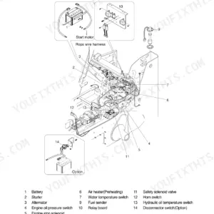
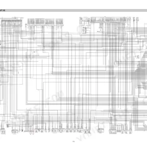
| Electrical System | 400-470 | Component Location |
Quick Reference Specifications
| Specification | Value | Page |
|---|---|---|
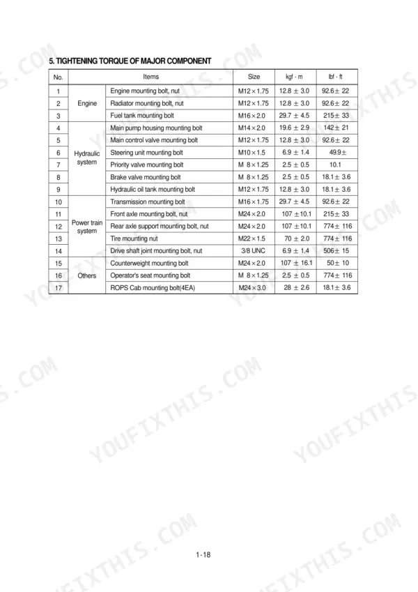
| Engine mounting bolt, nut | 12.8 ± 3.0 kgf·m | p. 18 |
| Radiator mounting bolt, nut | 12.8 ± 3.0 kgf·m | p. 18 |
| Operating pressure (Minimum) | 5.8 kgf/cm² (82.5 psi) | p. 24 |
| Relief pressure | 19~20Mpa (190~200bar, 2760~2900psi) | p. 262 |
| Pressure relief valve setting pressure | 195 ± 5 bar (2830 ± 73 psi) | p. 291 |
| Main relief valve pressure setting | 21 MPa | p. 309 |
| Bucket spool load check valve pressure setting | 24 MPa | p. 309 |
| Pressure reducing valve supply pressure | 30 bar | p. 315 |
| Bypass valve set pressure | 1.36kgf/cm2 (19.3psi) | p. 339 |
| Hydraulic oil filter replacement interval | 250 operating hours | p. 368 |
| Engine Oil Quantity | 14 L | p. 23 |
| Main Pump Maximum Operating Pressure | 210 kgf/cm2 | p. 23 |
Hyundai HL720-3 Common Problems This Manual Covers
Hyundai HL720-3 no steering and no hydraulic function, bucket dead at full throttle
Check the hydraulic tank sight glass before anything else; the system holds 45 L (page 258). With oil confirmed, tee a gauge into the main pump circuit and stall a function: you need 210 kgf/cm2 per the spec on page 359. Low pressure with a full tank points to a stuck-open main relief valve or a worn-out pump.
Manual Section: Steering System p. 238Steering wheel heavy at low idle, turns slow at high idle, gets worse when oil warms up
Test relief pressure at the steering unit before condemning the pump; the setting is 195 ± 5 bar (page 291). If the reading is low or erratic, pull the relief cartridge, flush out the dirt, and reinstall the plug at 5.1 kgf·m. A spool that only sticks when hot means the unit needs disassembly, covered from page 238.
Manual Section: Steering System p. 291Hydraulic oil foaming in the sight glass, milky oil and noisy pump on cold startup
Drain a sample and check for milkiness; water contamination means a full change of the 45 L system (page 258). Inspect every suction line clamp and fitting for air leaks, then verify the oil grade matches spec. Replace the return filter while the tank is open; the interval is 250 operating hours per page 368.
Manual Section: Work Equipment p. 368Boom and bucket slow or weak under load, functions fade once machine reaches operating temperature
Stall the boom against relief with a gauge on the pump outlet; you want 210 bar (page 330). Pressure that builds slowly or hunts means a worn pump or a contaminated main relief valve. If relief pressure checks good but functions stay weak, suspect internal cylinder leakage; boom cylinder dimensions are on page 24 for reseal work.
Manual Section: Work Equipment p. 330Boom float detent will not engage, lever kicks back out of float position
Verify pilot pressure first; the reducing valve should supply 30 to 35 bar (page 366). Below that, the detent cannot hold the spool in float. If pilot pressure checks good, pull the MCV boom spool and inspect for scoring or burrs binding it in the bore; the main control valve section starts at page 302.
Manual Section: Work Equipment p. 302Frequently Asked Questions
What are the torque specifications for the wheel loader?
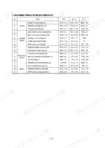
The tightening torque for major components varies by item. For example, the engine mounting bolt and nut (M12x1.75) require 12.8 ± 3.0 kgf·m (92.6 ± 22 lbf·ft), while the front axle mounting bolt and nut (M24x2.0) require 107 ± 10.1 kgf·m (774 ± 116 lbf·ft). p. 26
What are the replacement specifications for the hydraulic pump?
The main hydraulic pump is a fixed displacement gear type pump with a maximum delivery pressure of 210 kgf/cm² (2987 psi). The rated oil quantity is 125 l/min (33 U.S. gpm) at a rated speed of 2300 rpm. p. 23
What is the procedure for bleeding the service brake system?
Bleeding the service brake system requires two people. One person operates the brake valve while the other opens and closes the bleed screws. Push and hold the brake pedal down until the bleeding procedure is complete so no bubbles continue for more than 2 minutes. p. 230
What is the correct oil capacity for the engine oil pan?
The engine oil pan has a capacity of 14 liters (3.7 U.S. gallons). p. 23
What is the torque specification for the boom cylinder socket head bolts?
The socket head bolts (item 19, size M12x1.75x50) for the boom cylinder require a tightening torque of 9.4 ± 1 kgf·m (67.9 ± 7.2 lbf·ft). p. 392
What format is this Hyundai HL720-3 manual in?
All 470 pages arrive as one searchable PDF at checkout. Read it at the desk, then take the phone out to the machine.
Can I print this Hyundai HL720-3 manual?
Yes. Many buyers print one chapter at a time for their own shop and keep the rest on a tablet.








Reviews
There are no reviews yet.