

Part of the Hyundai Repair Manuals.
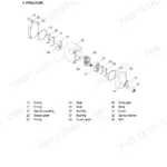
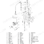
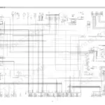
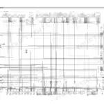
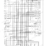
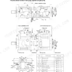
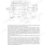
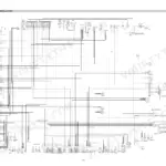
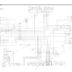
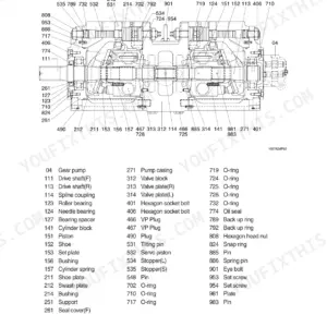
All 529 pages of this Hyundai R140LC-9, R140LCD-9, R140LCM-9 service manual PDF cover one machine family: the R140-9 hydraulic excavator, from the main pump to the undercarriage. Inside you get full electrical circuit diagrams with connector pinouts, hydraulic schematics for the main and pilot circuits (single and combined operation), and a self-diagnostic section that decodes the CAPO system's error codes. Step-by-step disassembly and assembly walks you through the pump device, main control valve, swing and travel drives, and every boom, arm, and bucket cylinder, backed by a complete component mounting torque section. Set the main relief for boom, arm, and bucket at 350 kgf/cm², then pull the swing bearing upper bolts to 41.3 kgf·m (299 lbf·ft). No more guessing which relief valve is bleeding off your breakout force. Text-searchable; find the spec, fix the machine.
What's Inside This Manual
| System | Pages | Key Topics |
|---|---|---|
| Foreword | 1 | Structure, Service Manual Purpose, Section Overview |
| How to Read the Service Manual | 2 | Distribution, Filing Method, Revised Edition Mark, Symbols |
| Conversion Table | 3-8 | Millimeters to Inches, Kilogram to Pound, Liter to U.S. Gallon, Temperature Conversion |
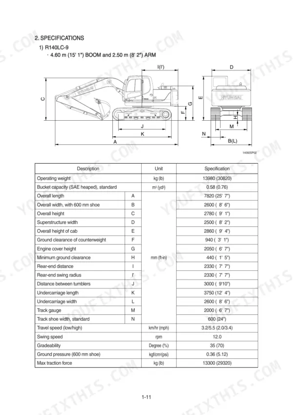
| General (Section 1) | 12-26 | Safety Hints, Major Components, Specifications, Working Range, Weight |
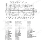
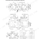
| Structure and Function (Section 2) | 49-129 | Pump Device, Regulator, Gear Pump, Main Control Valve, Swing Device, Travel Device, Rcv Lever, Rcv Pedal |
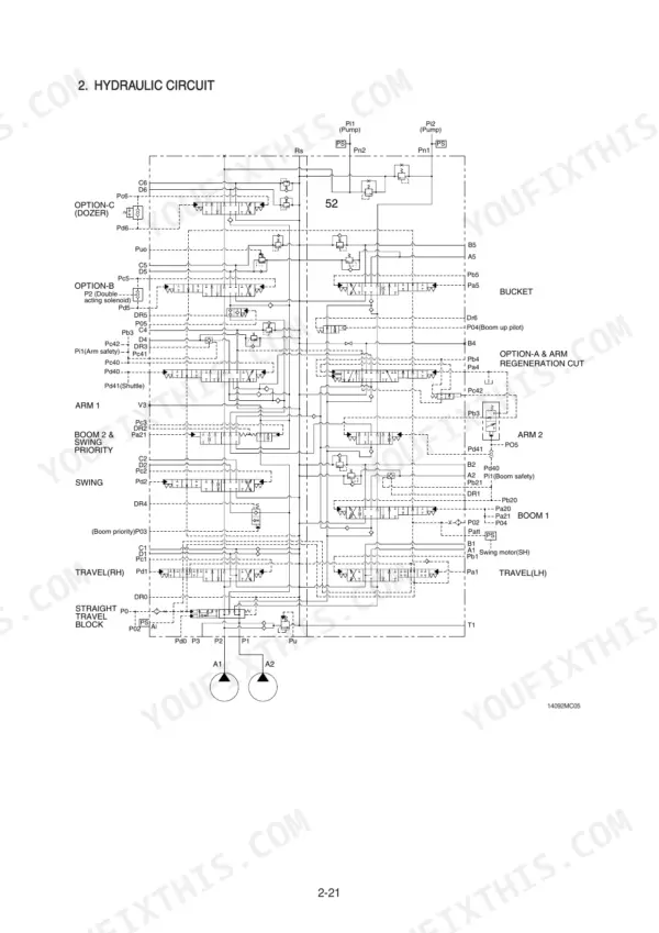
| Hydraulic System (Section 3) | 130-162 | Hydraulic Circuit, Main Circuit, Pilot Circuit, Single Operation, Combined Operation |
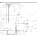
| Electrical System (Section 4) | 163-214 | Component Location, Electrical Circuit, Electrical Component Specification, Connectors |
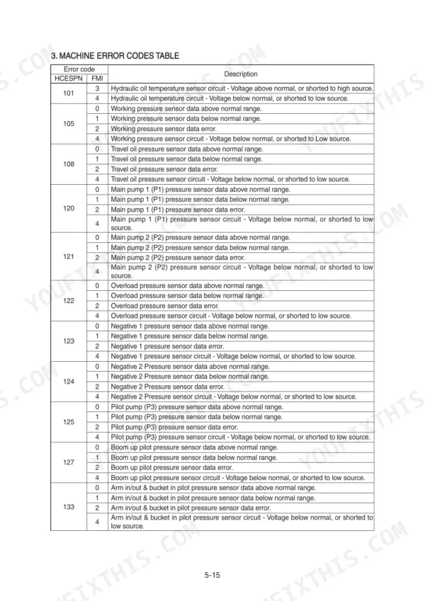
| Mechatronics System (Section 5) | 215-264 | Capo System Outline, Mode Selection, Automatic Deceleration, Engine Overheat Prevention, Self-Diagnostic System |
| Maintenance Standard (Section 7) | 335-369 | Operational Performance Test, Major Components, Track and Work Equipment |
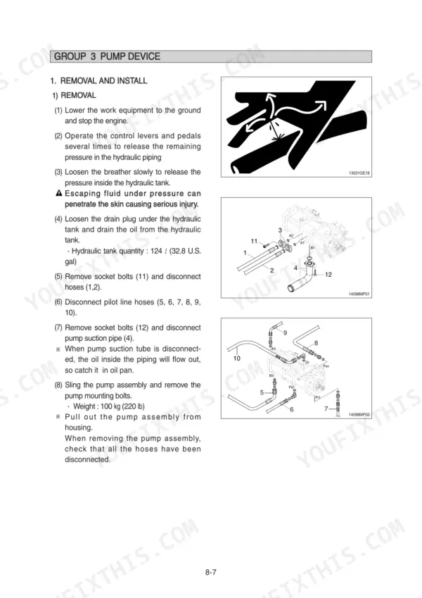
| Disassembly and Assembly (Section 8) | 370-514 | Precaution, Tightening Torque, Pump Device, Main Control Valve, Swing Device, Travel Device, Rcv Lever, Turning Joint |
| Component Mounting Torque (Section 9) | 515-529 | Introduction Guide, Engine System, Electric System, Undercarriage, Structure, Work Equipment |
Quick Reference Specifications
| Specification | Value | Page |
|---|---|---|
| All Models | ||
| Port relief setting at 20 lpm (Boom, Arm, Bucket) | 400 ± 10 kgf/cm² | p. 355 |
| Standard relief pressure (Boom, Arm, Bucket) | 350 (380) ± 10 kgf/cm² | p. 355 |
| Standard relief pressure (Travel) | 365 ± 10 kgf/cm² | p. 355 |
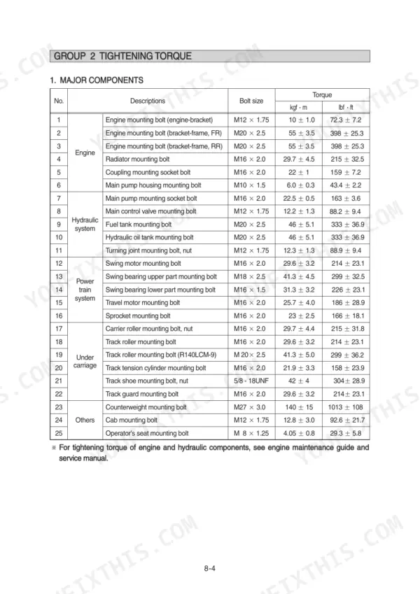
| Swing bearing upper part mounting bolt | 41.3 ± 4.5 kgf·m (299 ± 32.5 lbf·ft) | p. 375 |
| Swing bearing lower part mounting bolt | 31.3 ± 3.2 kgf·m (226 ± 23.1 lbf·ft) | p. 375 |
| Track roller mounting bolt | 29.6 ± 3.2 kgf·m (214 ± 23.1 lbf·ft) | p. 375 |
| Track roller mounting bolt (R140LCM-9) | 41.3 ± 5.0 kgf·m (299 ± 36.2 lbf·ft) | p. 375 |
| Overload relief valve tightening torque | 8~9 kgf·m (57.8~65.1 lbf·ft) | p. 411 |
| Tightening torque for M12x1.75 cylinder pins | 12.8±3.0 kgf·m (92.6±21.7 lbf·ft) | p. 529 |
| Tightening torque for M16x2.0 cylinder pins | 29.7±4.5 kgf·m (215±32.5 lbf·ft) | p. 529 |
| R140LC-9 | ||
| Operating Weight (R140LC-9) | 13980 kg | p. 23 |
| R140LCD-9 | ||
| Operating Weight (R140LCD-9) | 14800 kg | p. 25 |