

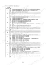
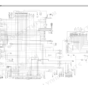
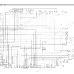
Part of the Hyundai Repair Manuals.
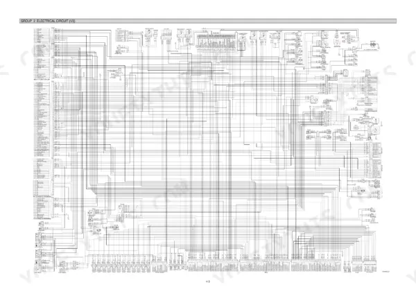
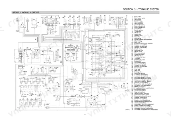
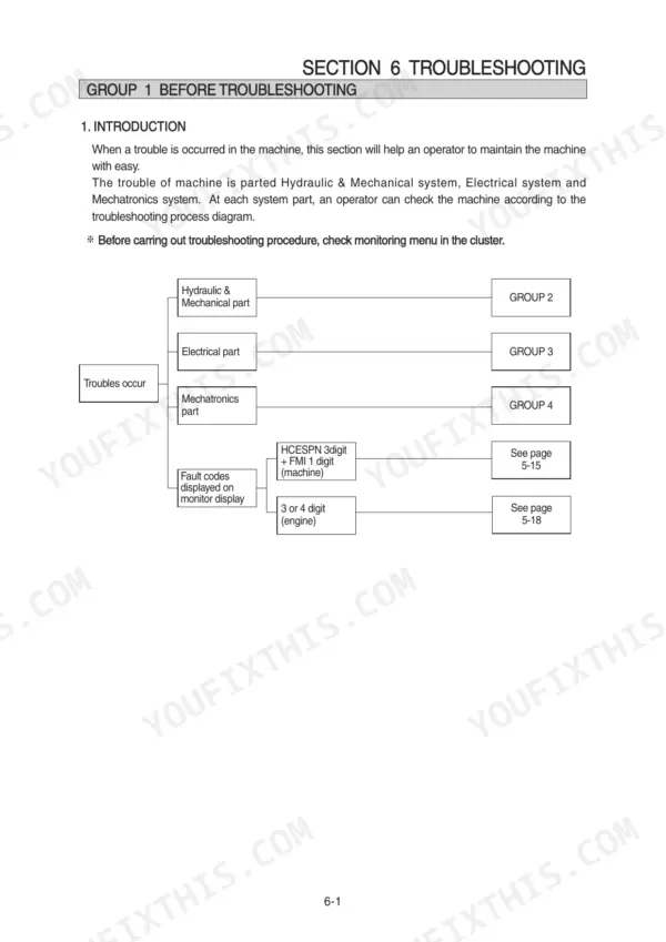
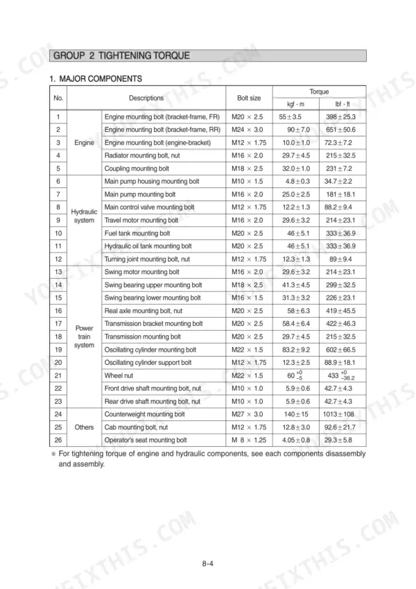
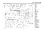
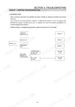
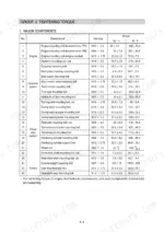
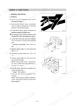
Looking for the complete Hyundai R140W-9 service manual PDF? All 679 pages of this factory manual cover the R140W-9 Wheel Excavator, from the pump device to the work equipment cylinders. You get full hydraulic schematics with main and pilot circuit routing, wiring diagrams with connector pinouts, and a heavy troubleshooting section spanning hydraulic, electrical, and mechatronics faults, including the self-diagnostic system. Step-by-step teardown procedures walk you through the main pump, swing motor, travel motor, powershift transmission, steering valve, and both axles. Set the swing bearing upper mounting bolts to 41.3 kgf·m; rear engine mount bolts get 90 kgf·m, and the engine holds 24 liters of oil. Your excavator is down, and forum guesses won't get it running. Bookmarked with a full text layer, this PDF opens on laptop, tablet, or phone: find the spec, walk to the machine, fix it.
What's Inside This Hyundai R140W-9 Manual
| System | Pages | Key Topics |
|---|---|---|
| General | 1-34 | Safety Hints, Specifications |
| Structure and Function | 35-121 | Pump Device, Main Control Valve, Swing Device, Travel Motor, Rcv Lever, Accelerator Pedal, Brake Pedal, Transmission |
| Hydraulic System | 122-154 | Hydraulic Circuit, Main Circuit, Pilot Circuit |
| Electrical System | 155-210 | Component Location, Electrical Circuit, Electrical Component Specification |
| Mechatronics System | 211-267 | Outline, Mode Selection System, Automatic Deceleration System |
| Troubleshooting | 268-348 | Before Troubleshooting, Hydraulic and Mechanical System, Electrical System, Mechatronics System |
| Maintenance Standard | 349-377 | Operational Performance Test, Major Components, Work Equipment |
| General Precautions and Tightening Torque | 378-408 | Removal Work, Installation Work, Tightening Torque Charts, Bolt Specifications |
| Pump Device | 409-421 | Main Pump Structure, Regulator Disassembly, Gear Pump Disassembly, Pump Assembly |
| Swing Device | 422-442 | Swing Motor Removal, Swing Motor Disassembly, Reduction Gear Disassembly, Swing Motor Assembly |
| Travel Motor | 443-466 | Travel Motor Removal, Motor Unit Structure, Control Unit Disassembly, Counter-Balance Valve |
| Transmission | 467-520 | Transmission Removal, Powershift Transmission Structure, Brake and Clutch Disassembly, Downshift Interlock |
| Steering Valve and Axles | 521-584 | Steering Valve Removal, Steering Cylinder Disassembly, Front Axle Removal, Rear Axle Removal |
| Work Equipment Cylinders | 585-663 | Bucket Cylinder Removal, Arm Cylinder Removal, Boom Cylinder Removal, Dozer Cylinder Removal |
| Component Mounting Torque | 664-679 | Introduction Guide, Engine System, Electric System, Power Train System, Structure, Work Equipment |
Quick Reference Specifications
| Specification | Value | Page |
|---|---|---|
| Swing bearing upper mounting bolt | 41.3 ± 4.5 kgf·m | p. 382 |
| Engine mounting bolt (bracket-frame, FR) | 55 ± 3.5 kgf·m | p. 382 |
| Engine mounting bolt (bracket-frame, RR) | 90 ± 7.0 kgf·m | p. 382 |
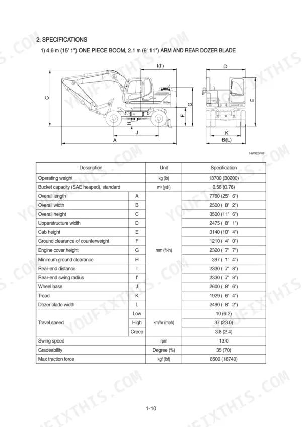
| Operating weight | 13700 kg | p. 22 |
| Engine oil quantity | 24 L | p. 30 |
| Main pump maximum pressure | 350 kgf/cm2 | p. 30 |
| Swing motor braking torque | 25 kgf·m | p. 31 |
| Travel motor relief pressure | 360 kgf/cm2 | p. 31 |
Hyundai R140W-9 Common Problems This Manual Covers
Hyundai R140W-9 boom and arm slow, jerky, or drifting down under load
Check hydraulic oil level and condition first; milky or dark oil means contamination. Verify main pump output reaches the 350 kgf/cm2 maximum with a gauge on the test port. If pressure is good, suspect cylinder seals; cylinder overhaul procedures start on page 585, and the troubleshooting flow covers the full circuit.
Manual Section: Hydraulic and Mechanical SystemEngine oil pressure warning lamp and buzzer come on shortly after start or while working
Stop the engine immediately, do not idle it down. Check the dipstick; this engine holds 24 L of oil, listed on page 30. Top up if low and inspect for leaks at the filter and drain plug. If the lamp stays on with correct level, test the pressure sender and wiring using the procedures starting.
Manual Section: Electrical System p. 155Travel power weak on grades, machine pulls to one side or crawls at full throttle
Test travel circuit relief pressure with a gauge; it should hit 360 kgf/cm2. Anything lower points to a stuck relief valve or worn motor unit. Inspect the counter-balance valve for a sticking spool, then check tire sizes match side to side. Travel motor disassembly and control unit procedures begin on page 443.
Manual Section: Travel Motor p. 443Upper structure creeps when parked across a slope, swing brake will not hold position
Verify swing motor braking torque against the 25 kgf·m spec on page 31 before pulling anything apart. Check pilot pressure at the brake release port; residual pressure keeps the brake released. If torque is under spec, disassemble the swing motor and inspect brake friction plates and springs, following the swing device procedures from page 422.
Manual Section: Swing Device p. 422Heavy vibration through the cab and frame at idle, gets worse under load
Inspect engine mounting hardware before chasing internal faults. Torque the engine-to-bracket bolts to 10.0 kgf·m, the front bracket-to-frame bolts to 55 kgf·m, and the rears to 90 kgf·m; the torque chart on page 382 lists all three. Replace any crushed or oil-soaked rubber mounts, and check the fan belt for glazing while you are in there.
Manual Section: General Precautions and Tightening Torque p. 382Frequently Asked Questions
What are the fault codes for the engine oil pressure warning lamp?
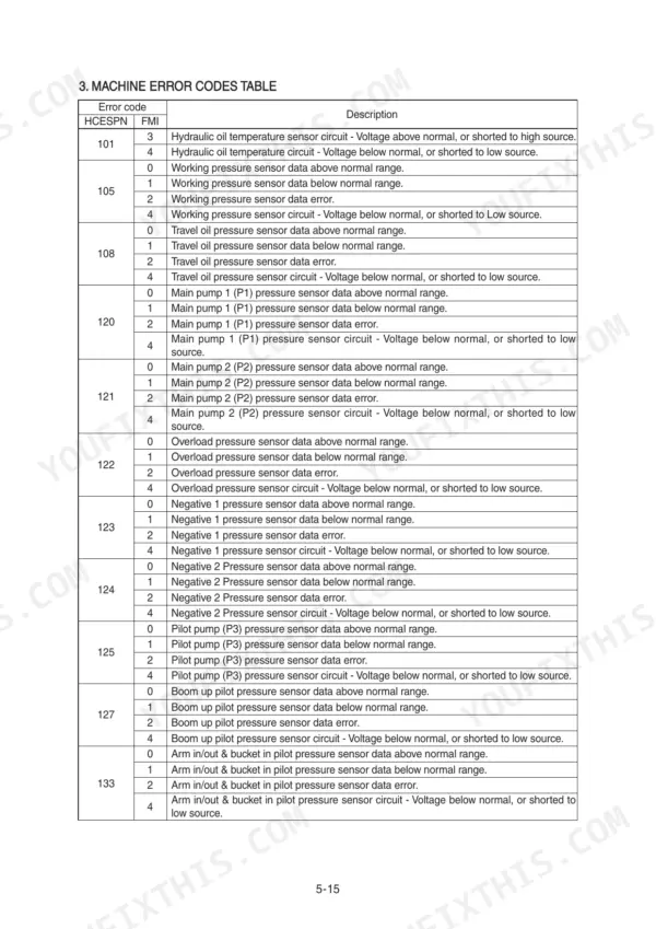
The fault codes for the engine oil pressure warning lamp are HCESPN 135 (FMI 3 or 4) and HCESPN 304 (FMI 3 or 4). If these codes are active, check the engine oil pressure sensor and related wiring connections as described in the troubleshooting section. p. 298
What is the tightening torque for the swing bearing upper mounting bolt?
The tightening torque for the swing bearing upper mounting bolt (M18 x 2.5) is 41.3 ± 4.5 kgf·m (299 ± 32.5 lbf·ft). p. 382
What is the replacement interval for the hydraulic oil return filter?
The replacement interval for the hydraulic oil return filter is every 1000 hours. p. 260
What is the engine oil capacity for the R140W-9?
The engine oil capacity for the R140W-9 is 24 liters (6.3 U.S. gal). p. 30
What is the procedure for bleeding air from the hydraulic pump?
To bleed air from the hydraulic pump, remove the air vent plug (2EA), tighten it lightly, start the engine at low idling until oil comes out from the plug, and then tighten the plug fully. p. 386
Do I get instant access to this Hyundai R140W-9 Service Manual?
A single searchable PDF file of 679 pages, downloadable right after payment. Nothing ships, nothing waits in the mail.
Am I free to print this Hyundai R140W-9 Service Manual?
Yes. Many buyers print one chapter at a time for their own shop and keep the rest on a tablet.








Reviews
There are no reviews yet.