
Part of the Hyundai Repair Manuals.
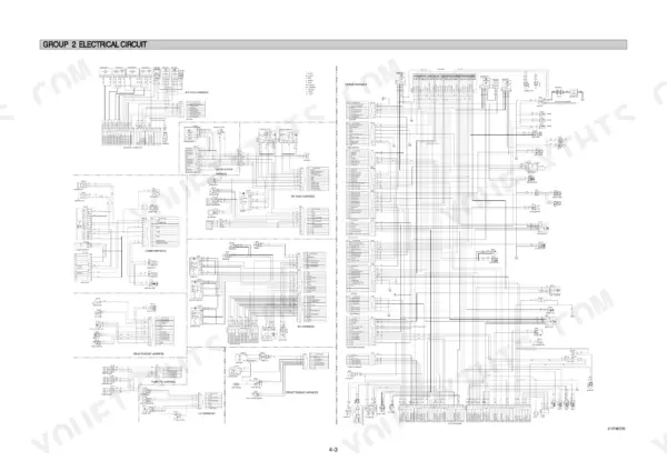
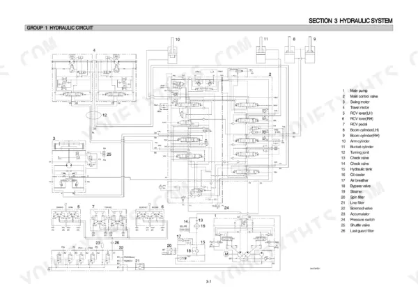
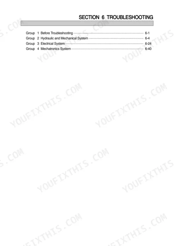
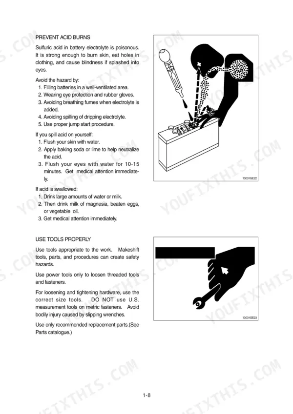
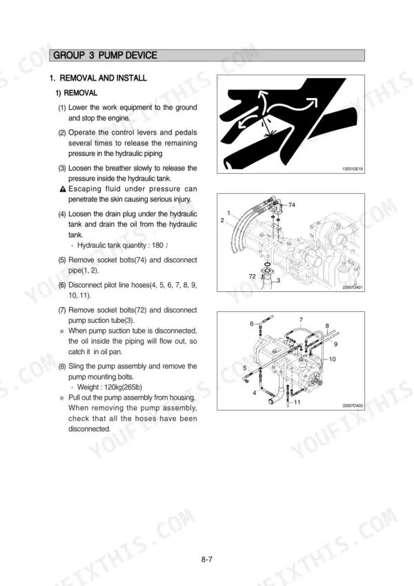
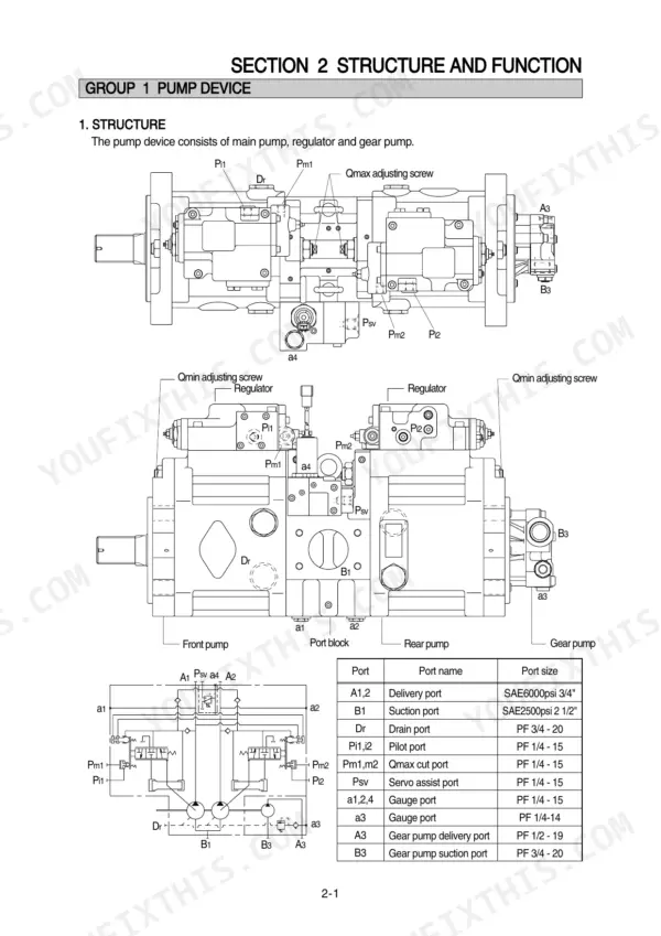
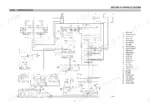
Wrenching on a Hyundai R210LC-7? This 481-page Hyundai R210LC-7 shop manual PDF covers the standard hydraulic excavator and the Long Reach variant, straight from the factory. Inside: full hydraulic circuit schematics with pilot and main circuit routing, complete electrical wiring diagrams with connector pinouts, and page after page of disassembly and assembly procedures for the pump device, main control valve, swing and travel drives. You also get the mechatronics section that decodes the self-diagnostic system, power boost, and auto-deceleration logic. Set the pilot relief valve at 35 kgf/cm2 and confirm both 12V, 100Ah batteries before blaming the starter. No more diagnosing hydraulic faults with a gauge and a hunch. Bookmarked with a working text layer; jump to any section or search any spec right from the tablet in your cab.
Other edition of this manual
What's Inside This Hyundai R210LC-7, R210LC-7 LONG REACH Manual
| System | Pages | Key Topics |
|---|---|---|
| General | 12-39 | Safety Hints, Specifications |
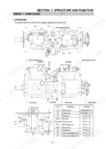
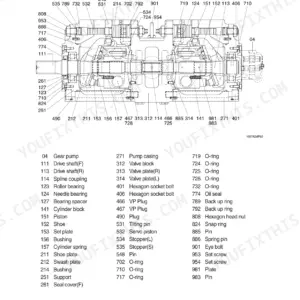
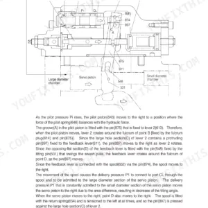
| Structure and Function | 40-129 | Pump Device, Main Control Valve, Swing Device, Travel Device, Rcv Lever, Rcv Pedal |
| Hydraulic System | 130-161 | Hydraulic Circuit, Main Circuit, Pilot Circuit, Single Operation, Combined Operation |
| Electrical System | 162-210 | Component Location, Electrical Circuit, Electrical Component Specification, Connectors |
| Mechatronics System | 211-253 | Outline, Mode Selection System, Automatic Deceleration System, Power Boost System, Travel Speed Control System, Automatic Warming Up Function, Engine Overheat Prevention Function |
| Maintenance Standard | 310-344 | Operational Performance Test, Major Components, Track and Work Equipment |
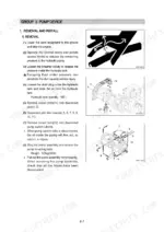
| Disassembly and Assembly | 345-465 | Precaution, Tightening Torque, Pump Device, Main Control Valve, Swing Device, Travel Device, Rcv Lever, Turning Joint |
| Component Mounting Torque | 466-481 | Introduction Guide, Engine System, Electric System, Undercarriage, Structure, Work Equipment |
Quick Reference Specifications
| Specification | Value | Page |
|---|---|---|
| All Models | ||
| Bypass relief valve opening pressure | 1.5kgf/cm2 (21psi) | p. 133 |
| Pilot relief valve setting pressure | 35kgf/cm2 | p. 135 |
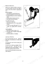
| Battery | 12V x 100Ah (2EA) | p. 181 |
| Starter | Delco Remy 28MT 24V | p. 187 |
| Voltage | 24V | p. 290 |
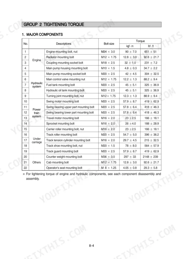
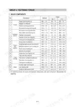
| Main pump mounting socket bolt | 42 ± 4.5 kgf·m | p. 350 |
| Main relief valve tightening torque | 7~8 kgf·m (50.6~57.8 lbf·ft) | p. 386 |
| Port relief valve tightening torque | 7~8 kgf·m (50.6~57.8 lbf·ft) | p. 386 |
| Engine Oil Quantity | 24 L | p. 35 |
| Battery Capacity | 2 x 12V x 100Ah | p. 35 |
| R210LC-7 | ||
| Operating Weight, R210LC-7 | 21700 kg | p. 23 |
| R210LC-7 LONG REACH | ||
| Operating Weight, R210LC-7 LONG REACH | 24360 kg | p. 24 |
Hyundai R210LC-7, R210LC-7 LONG REACH Common Problems This Manual Covers
Hyundai R210LC-7 boom and arm weak or slow, bucket lacks digging power
Check hydraulic oil level and inspect the tank filter first; a clogged element opens the bypass at 1.5 kgf/cm2 (21 psi) and starves the pump. Test main relief pressure against the 330 kgf/cm2 spec on page 36. If pressure stays low, adjust or replace the main relief valve and torque it to 7~8 kgf·m on reassembly.
Manual Section: Hydraulic and Mechanical System Troubleshooting p. 258Hydraulic pump whines or growls under load and all cylinder speeds drop noticeably
Check oil level in the sight glass and top up before anything else; cavitation from low oil kills pumps fast. Inspect the suction line for air leaks and replace a collapsed filter element, since the bypass opens at only 1.5 kgf/cm2 (21 psi), noted on page 133. After any pump removal, torque the mounting socket bolts to 42 ± 4.5 kgf·m.
Manual Section: Hydraulic and Mechanical System Troubleshooting p. 258Engine cranks slowly or refuses to start, especially on cold mornings after sitting overnight
Test both 12V 100Ah batteries under load; the series pair must deliver a full 24V to the Delco Remy 28MT starter, spec'd on page 187. Clean and tighten the ground cables at the frame, then check voltage drop across the starter relay. Follow the no-start checks beginning before condemning the starter itself.
Manual Section: Engine TroubleshootingHydraulic oil temperature climbs and the warning lamp comes on during normal digging
Check oil level first, then blow out the hydraulic cooler fins from the engine side with compressed air; caked mud cuts airflow badly. Verify fan belt tension and confirm system pressure is not riding the 330 kgf/cm2 relief setting on page 36 all cycle, because constant relieving dumps heat straight into the oil.
Manual Section: Hydraulic and Mechanical System Troubleshooting p. 258Machine pulls to one side and travels in a curve on flat ground
Compare track sag on both sides and adjust tension equally before touching the hydraulics. Swap the travel lines side to side at the turning joint to see whether the fault follows the motor or stays with the valve. Check pilot pressure against the 35 kgf/cm2 setting on page 135; a weak pilot supply causes uneven spool shift.
Manual Section: Hydraulic and Mechanical System Troubleshooting p. 258Frequently Asked Questions
How do I clear a recorded fault code on the Hyundai R210LC-7 excavator?
To delete all recorded error codes, select the recorded error (TIME Er) display on the cluster. Press the engine and select switches at the same time for 2 seconds or more. The cluster display will change to 'TIME Er : 00', indicating that the CPU controller has deleted all recorded error codes from the memory. p. 223
What is the torque specification for the track roller mounting bolts on the R210LC-7?
The tightening torque for the track roller mounting bolts (M20 x 2.5) is 54.7 ± 5.0 kgf·m (396 ± 36.2 lbf·ft). p. 349
What is the standard torque for the engine mounting bolts on the R210LC-7?
The engine mounting bolts (M24 x 3.0) should be tightened to a torque of 90 ± 7.0 kgf·m (651 ± 51 lbf·ft). p. 349
What is the procedure for bleeding air from the hydraulic pump after installation?
After installation, remove the air vent plug (2EA) from the hydraulic pump. Tighten the plug lightly, start the engine at low idling, and check that oil comes out from the plug. Once oil flows, tighten the plug fully. p. 353
What is the standard resistance for the engine speed sensor?
The standard resistance for the engine speed sensor is 300 ± 30 KΩ. p. 236
How will I receive this Hyundai R210LC-7 Shop Manual?
Instant PDF download. You get the full 481-page searchable Shop Manual immediately after payment. Open it on your laptop, tablet, or phone right in the shop.
Is printing allowed for this Hyundai R210LC-7 Shop Manual?
Yes. Print a chapter or just the pages for the job at hand, for use in your own shop. Any home or office printer works.






Reviews
There are no reviews yet.