

Part of the Hyundai Repair Manuals.
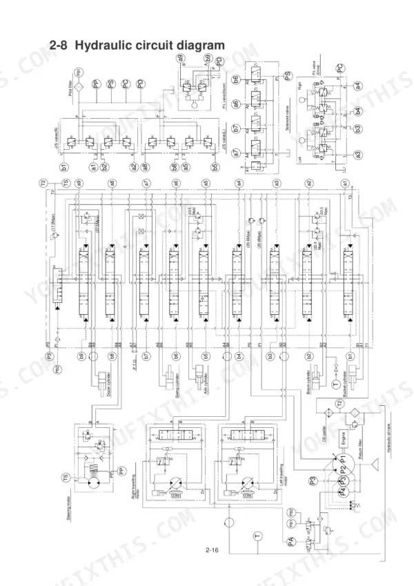
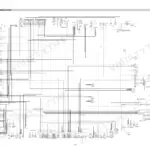
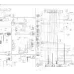
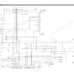
All 138 pages of this Hyundai R36N-7 (Robex 36N-7) Service Manual PDF cover one machine: the R36N-7 hydraulic excavator, from main pump to track roller. Inside: a full hydraulic circuit diagram, an electric circuit diagram for chasing starter and alternator faults, and page after page of disassembly and assembly procedures for the control valve, slew motor, travel motor, and hydraulic cylinders. You also get a complete troubleshooting section that walks through weak operating power, dead boom and arm functions, and travel and slewing problems. Set both main relief valves to 20.6 MPa, then torque the port relief valve cap nut to 30 N-m when you button the control valve back up. No more chasing hydraulic faults with a gauge and a hunch. The PDF is bookmarked with a live text layer; search any spec, jump straight to your section, and get wrenching.
What's Inside This Hyundai R36N-7 Manual
| System | Pages | Key Topics |
|---|---|---|
| Precautions on Maintenance | 6 | Correct Operation, Precautions on Operation, Safety Check, Preparation, Efficiency, Assembly |
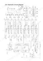
| Outline | 7-24 | Location of Serial Number, Name of Each Part, Dimensions and Specification, Weight List, Oil and Grease Supply Points, Hydraulic Circuit Diagram |
| Attachment | 25-32 | Standard of Maintenance, Inspection and Adjustment, Measuring the Fall of the Attachment, Measuring the Speed of the Attachment Cylinder |
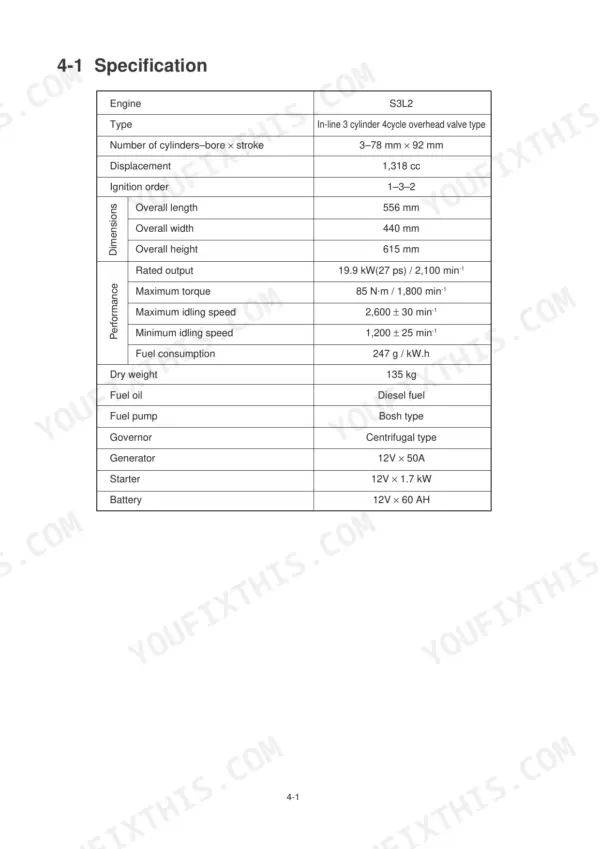
| Engine | 33-44 | Specification, Performance Curve, Location of Serial Number, Standard Engine Speed, Inspection and Maintenance Procedures |
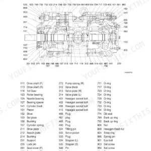
| Main Pump | 45-52 | Specification, Structure, Removing and Installing the Pump, Performance Test of the Hydraulic Pump, P-Q Characteristic Curve |
| Hydraulic Oil Filter | 53-58 | Installation, Line Filter, Suction Filter, Pilot Filter, Maintenance Procedure |
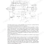
| Control Valve | 59-66 | Specification, Disassembly and Assembly, Structure of the Relief Valve, Precautions for Handling |
| Joystick (Pilot Valve) | 67-69 | Specification, Secondary Pressure and Push-Rod Stroke, Single- and Double-Operating Torque, Port Plate and Structure |
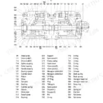
| Pilot Valve (1) (Travel) | 70-73 | Specification, Structure and Exploded View with Numbered Part Callouts |
| Pilot Valve (2) (Dozer) | 74-77 | Specification with Secondary Pressure and Operating Torque Curves, Structure and Exploded View |
| Slew Motor | 78-83 | Slew Bearing and Slew Case Wear Limits, Measuring Natural Slew Distance, Measuring Over-Slew Distance After Stopping, Measuring Required Slewing Time, Motor Specification and Structure |
| Travel Motor | 84-89 | Handling the Travel Motor, Measuring Travel Motor Idling, Motor Specification and Structure, Inspection and Adjustment |
| Hydraulic Cylinder | 90-95 | Structure, Disassembly Procedure, Disassembling Inner Parts, Assembly and Inspection Procedure |
| Swivel Joint | 96-99 | Specification and Structure, Disassembly and Assembly |
| Crawler | 100-107 | Structure and Operation, Standard of Maintenance, Disassembly and Assembly |
| Spring Case and Grease Cylinder | 108-111 | Structure, Specification of Spring, Disassembly and Assembly |
| Idler | 112-113 | Standard of Maintenance, Outer Diameter of Tread, Width of Projected Part, Overall and Tread Width, Lubricating Oil Grade and Quantity |
| Sprocket | 114-117 | Disassembly and Assembly, Removing the Sprocket, Installing the Sprocket, Standard of Maintenance |
| Track Roller | 118-119 | Standard of Maintenance, Outer Diameter of Projected Part and Tread, Overall and Tread Width, Mounting Bolt Tightening Torque, Lubricating Oil Quantity |
| Carrier Roller | 120-121 | Standard of Maintenance, Outer Diameter, Overall Width, Mounting Bolt Tightening Torque, Lubricating Oil Quantity |
| Electrical Equipment | 122-125 | Structure and Function, Electric Circuit Diagram, Failure and Remedy, Starter System, Alternator System |
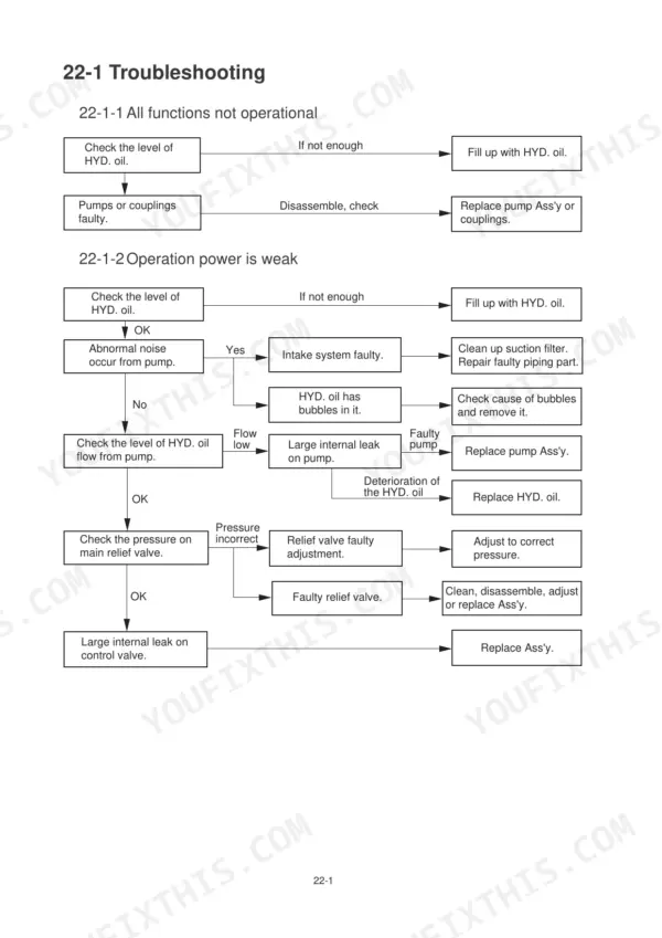
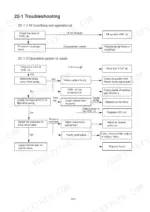
| Troubleshooting | 126-138 | All Functions Not Operational, Operation Power Is Weak, No Operation on Boom, Arm, Bucket and Slewing, Travelling System, Slewing System |
Quick Reference Specifications
| Specification | Value | Page |
|---|---|---|
| Main relief P1 | 20.6 MPa | p. 24 |
| Main relief P2 | 20.6 MPa | p. 24 |
| Pump capacity P1 | 17.5 cc/rev | p. 24 |
| Pump capacity P2 | 17.5 cc/rev | p. 24 |
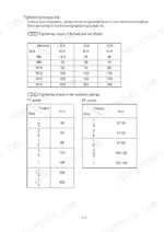
| Port relief valve cap nut tightening torque | 30 N·m | p. 65 |
| Port relief valve installation torque | 70 N·m | p. 65 |
| Line filter (only P.T.O return) tightening torque | 20 N·m | p. 56 |
| Pilot filter tightening torque | 60-80 N·m | p. 56 |
| Tightening torque of sprocket mounting bolt | 100 N·m ~ 110 N·m | p. 115 |
| Tightening torque of motor mounting bolt | 100 N·m ~ 110 N·m | p. 115 |
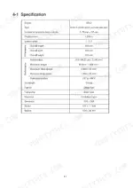
| Engine Rated Output | 19.9 kW (27.0 PS) / 2400 min-1 | p. 11 |
| Hydraulic Tank Capacity | 42.0 L | p. 11 |
Hyundai R36N-7 Common Problems This Manual Covers
Hyundai Robex36N-7 all hydraulic functions weak, boom and bucket slow with pump whining under load
Check the weak-power chart in the troubleshooting procedures on page 127 first. Test main relief pressure at P1 and P2; spec is 20.6 MPa. Adjust the relief valve knowing one full rotation changes pressure by 17.7 MPa per page 66, then torque the cap nut to 30 N·m. Bleed air from the suction line if the pump whines.
Manual Section: Operation power is weak p. 127Boom creeps down under load with pilot valve in neutral, bucket sinks overnight
Verify the boom circuit relief pressure reaches 20.6 MPa before condemning parts. If pressure checks good, inspect the hydraulic cylinder for internal leakage using the inspection procedure starting on page 90, and replace the piston seals if oil bypasses. Reset the port relief to 23.5 MPa if it cracks early, then torque the cap nut to 30 N·m.
Manual Section: Boom system p. 60Machine won't travel in either direction, engine runs fine but crawlers stay completely dead
Check hydraulic tank oil level first; the tank holds 42.0 L and a low tank starves the pump. Pull the suction filter and clean the screen, following the filter procedures starting on page 53. Next inspect the engine coupling for shredded elastic plates. If those check out, test the main pump; mounting bolts torque to 90-115 N·m on reinstall.
Manual Section: Travelling system p. 53Hydraulic oil running hot, pump housing too hot to touch after an hour of digging
Drain and inspect the hydraulic oil; refill with 42.0 L of clean fluid if it smells burnt or looks milky. Replace the line filter and torque it to 20 N·m, then clean the pilot filter and torque it to 60-80 N·m per page 56. Run a pump performance test per the procedure starting on page 45 if heat persists.
Manual Section: Main Pump p. 45Upper structure drifts after slewing stops, won't hold swing position on a slope
Test the slew circuit relief pressure; spec is 15.7 MPa. Adjust at the relief valve, where one rotation changes pressure by 15.7 MPa per page 66, and torque the cap nut to 30 N·m when finished. If pressure holds but drift continues, check the slew motor against the maintenance standards starting on page 78.
Manual Section: Slewing system p. 79Frequently Asked Questions
What are the torque specifications for the track rollers, sprocket, and swing bearing on the Hyundai Robex 36N-7?
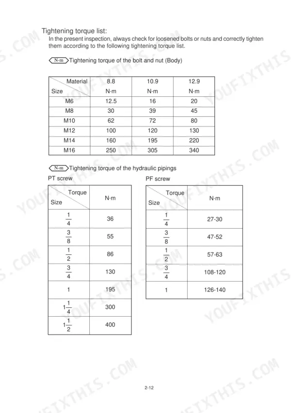
The tightening torque for the track roller mounting bolt is 325 N·m (page 119). The sprocket mounting bolt and motor mounting bolt both require a tightening torque of 100–110 N·m (page 116). The slew bearing is not explicitly listed with a single torque value, but the slew motor mounting bolts are specified at 250 N·m for M16 bolts (page 81). p. 119
What are the replacement specifications for the main relief valve?
The main relief pressure for P1 and P2 is 20.6 MPa at 42 L/min, and for P3 it is 17.2 MPa at 25 L/min (page 60). The tightening torque for the relief valve cap nut is 30 N·m, and the installation torque for the relief valve itself is 70 N·m (page 65). p. 60
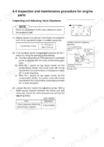
What is the correct valve clearance for the engine?
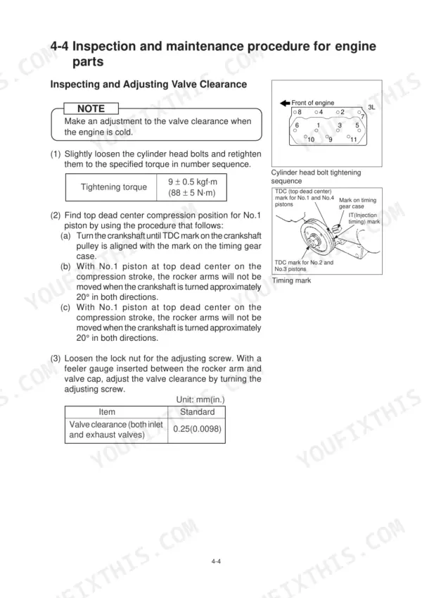
The valve clearance for both inlet and exhaust valves should be adjusted to 0.25 mm (0.0098 in.) when the engine is cold. p. 37
What is the required tightening torque for the cylinder head bolts?
The cylinder head bolts must be tightened to a torque of 9 ± 0.5 kgf·m (88 ± 5 N·m) in the specified number sequence. p. 37
What is the capacity of the hydraulic tank?
The total capacity of the hydraulic tank is 42 liters. p. 11
What exactly do I receive with this Hyundai Robex36N-7 Service Manual?
You download the Service Manual yourself: 138 pages, searchable PDF, available immediately. Keep a copy on every device you use.
Can I print pages of this Hyundai Robex36N-7 manual for my own shop?
Yes. Printing works from any reader and any printer, for your own shop use.






Reviews
There are no reviews yet.