

Part of the Hyundai Repair Manuals.
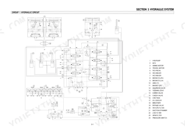
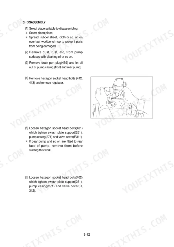
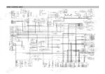
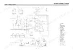
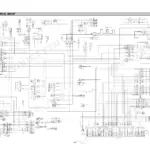
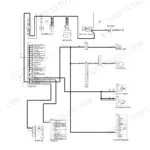
Every one of the 455 pages in this Hyundai R360LC-3 Shop Manual PDF is aimed at one machine: your R360LC-3 hydraulic excavator, from the pump device to the swing motor. You get complete hydraulic schematics for the main and pilot circuits, factory wiring diagrams with connector layouts and component locations, a full troubleshooting section, and step-by-step disassembly and assembly procedures for the pump, main control valve, swing device, turning joint, and boom, arm and bucket cylinders. Mechatronics coverage too: mode selection, automatic deceleration, and engine control systems. Set the main relief valve at 320 kg/cm2 (4550 psi) and confirm each pump section is putting out 290 l/min at rated speed. No more chasing pilot-pressure gremlins with borrowed specs. Bookmarked with a live text layer; search any spec, jump straight to the fix, and get back on the sticks.
What's Inside This Hyundai R360LC-3 Manual
| System | Pages | Key Topics |
|---|---|---|
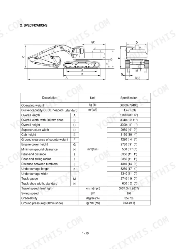
| General | 9-28 | Safety, Specifications |
| Structure and Function | 29-111 | Pump Device, Main Control Valve, Swing Device, Travel Device, Rcv Lever, Rcv Pedal |
| Hydraulic System | 112-141 | Hydraulic Circuit, Main Circuit, Pilot Circuit, Combined Operation |
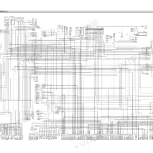
| Electrical System | 142-191 | Component Location, Electrical Circuit, Connectors |
| Mechatronics System | 192-220 | Outline, Mode Selection System, Automatic Deceleration System, Engine Control System |
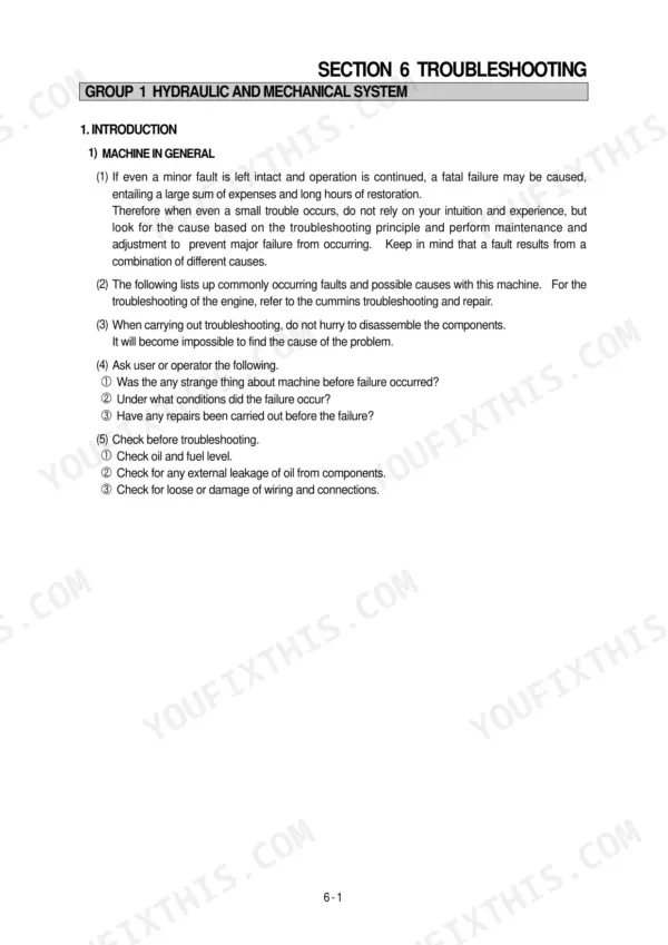
| Troubleshooting | 221-281 | Hydraulic and Mechanical System, Electrical System, Test Procedures |
| Maintenance Standard | 282-319 | Operational Performance Test, Major Component, Track and Work Equipment |
| Disassembly and Assembly | 320-455 | Precautions, Pump Device, Main Control Valve, Swing Device, Turning Joint, Boom, Arm and Bucket Cylinder, Work Equipment |
Quick Reference Specifications
| Specification | Value | Page |
|---|---|---|
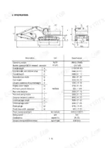
| Main pump capacity | 2 x 145 cc/rev | p. 25 |
| Main pump maximum pressure | 320 kg/cm2 (4550 psi) / 350 kg/cm2 (4980 psi) | p. 25 |
| Main relief valve pressure | 320 kg/cm2 (4550 psi) / 350 kg/cm2 (4980 psi) | p. 26 |
| Overload relief valve pressure | 380 kg/cm2 (5405 psi) | p. 26 |
| Bypass relief valve opening pressure | 1.27kg/cm2 | p. 114 |
| Drain oil pressure limit | 1.07kg/cm2 | p. 115 |
| Bypass check valve setting pressure | 3.0kg/cm2 | p. 114 |
| Pilot relief valve setting pressure | 40kg/cm2 | p. 116 |
| EPPR valve pressure gauge capacity | 0 to 40-50 kg/cm2 (0 to 570-710 psi) | p. 219 |
| EPPR valve pressure specification | 10-33 kg/cm2 (142-470 psi) | p. 219 |
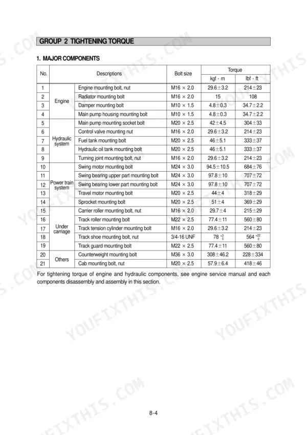
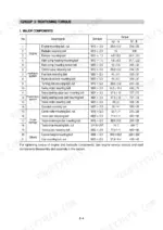
| Main pump housing mounting bolt | 4.8 ± 0.3 kgf·m | p. 323 |
Hyundai R360LC-3 Common Problems This Manual Covers
Hyundai R360LC-3 all hydraulic functions weak, digging and travel power low, won't build normal working pressure
Test main relief pressure at the pump gauge port with attachments stalled over relief. Boom, arm, and bucket circuits should read 320+5 kgf/cm2 per the maintenance standard on page 302. Adjust the main relief valve to spec; if pressure still won't come up, work through the troubleshooting procedures starting and inspect the pump for wear.
Manual Section: Hydraulic and Mechanical System Troubleshooting p. 302Boom drifts down or arm crawls with controls in neutral, load settles slowly
Check the overload relief valves on the affected circuit first; the overload setting is 380+5 kgf/cm2 per page 302, and one opening early bleeds the cylinder down. Then test for internal cylinder leakage: raise the boom, shut the engine off, and watch for drift. Replace cylinder seals using the disassembly procedures beginning on page 320.
Manual Section: Maintenance Standard p. 302Hydraulic oil overheats during normal digging cycles, oil temperature warning lamp comes on within an hour
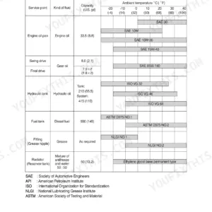
Clean the oil cooler core and verify fan operation before condemning the pump. Replace the return filter; its bypass relief opens at only 1.27 kg/cm2 (page 114), so a plugged element sends hot, dirty oil straight back to tank. Drain and refill with clean oil, 350 L (92.5 gal) tank capacity per page 28, then recheck operating temperature.
Manual Section: Hydraulic and Mechanical System Troubleshooting p. 114Pilot controls erratic or dead, attachment functions won't respond though engine runs fine
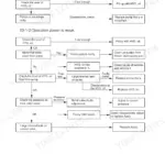
Test pilot pressure at the remote control valve inlet; the pilot relief valve is set at 40 kg/cm2 (page 116). If pilot pressure checks good, the fault is downstream: work the electrical troubleshooting flows in Section 6 Group 2 (pages 241-281), which walk the connector and harness tests circuit by circuit. Replace any coil out of spec, then inspect connector grounds and harness chafe points.
Manual Section: Electrical System Troubleshooting p. 116Power mode sluggish, engine speed hunts or machine drops into slow speed for no reason
Measure EPPR valve coil resistance; spec is 24 ± 1 Ω at 20°C per page 258. Then tee a gauge into the EPPR outlet and confirm 17-23 kg/cm2 output pressure (page 259) with the engine running. Clean or replace the valve if pressure hunts, and check the governor motor and potentiometer linkage for binding.
Manual Section: Mechatronics System Troubleshooting p. 259Frequently Asked Questions
How do I troubleshoot a no-start condition on a Hyundai R360LC-3?
To troubleshoot a no-start condition, first check the battery voltage and specific gravity (MIN 1.28). If the engine does not start, check the operation of the start motor and start relay, and verify the voltage at the starter magnet coil (20-30V). Detailed diagnostic steps and wiring diagrams are provided on page 251. p. 251
What are the replacement specifications for the Main relief valve?
The main relief valve is assembled as a cartridge. The normal pressure setting for the boom, arm, and bucket is 320+5 kgf/cm² (350+5 kgf/cm² with power boost), and 380+5 kgf/cm² for overload. For the swing function, the normal pressure is 260 kgf/cm². p. 302
What is the tightening torque for the engine mounting bolts on the R360LC-3?
The engine mounting bolts and nuts (M16 x 2.0) should be tightened to a torque of 29.6 ± 3.2 kgf·m (214 ± 23 lbf·ft). p. 323
How do I bleed the air from the hydraulic cylinders after repair?
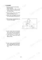
After reassembling, start the engine and run at low idling. Operate the control lever to actuate the hydraulic cylinder 4-5 times, stopping 100mm before the end of the stroke, then operate the piston rod to the end of its stroke to relieve the circuit. p. 321
What is the standard clearance for the track roller shaft and bushing?
The standard clearance between the track roller shaft and bushing is 0.29 to 0.395 mm, with a clearance limit of 1.5 mm. If the clearance exceeds this limit, the bushing should be replaced. p. 314
Is this Hyundai R360LC-3 Shop Manual a digital download?
Immediate download of the complete 455-page searchable Shop Manual. Access it on any device, from a laptop at your desk to a phone in the field.
Can I print specific sections of this Hyundai R360LC-3 Shop Manual?
Yes. Print a chapter or just the pages for the job at hand, for use in your own shop. Any home or office printer works.








Reviews
There are no reviews yet.