
Part of the Hyundai Repair Manuals.
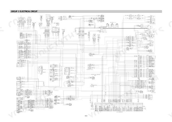
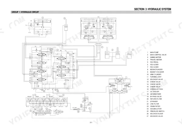
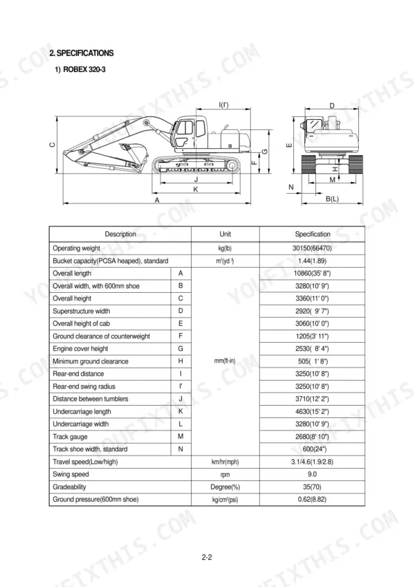
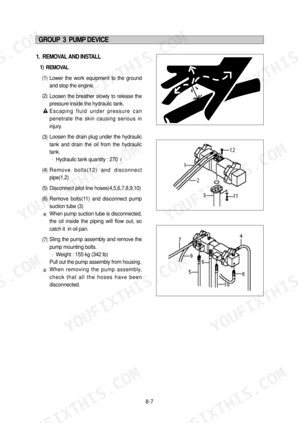
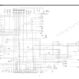
Wrenching on a Hyundai Robex hydraulic excavator? This 480-page shop manual PDF covers the 320-3, 320LC-3, and 320NLC-3, from pump device to final drive. Inside: a high-detail hydraulic section tracing main and pilot circuits through every combined operation, plus full electrical coverage with wiring circuits, connector layouts, and monitoring system diagnostics. You also get a mechatronics chapter that decodes mode selection, auto deceleration, and power boost, then troubleshooting charts, tightening torques, and operational performance tests to prove your repair worked. Each main pump moves 130 cc/rev at up to 320 kg/cm2 (4,550 psi); check your rated flow against 2 x 260 L/min before condemning a pump. No more chasing pilot pressure faults on forum guesses. Bookmarked with a live text layer, this PDF opens on any device; search a spec, find the number, get back in the seat.
What's Inside This Hyundai ROBEX 320-3, ROBEX 320LC-3, ROBEX 320NLC-3 Manual
| System | Pages | Key Topics |
|---|---|---|
| General | 1-47 | Safety, Specification |
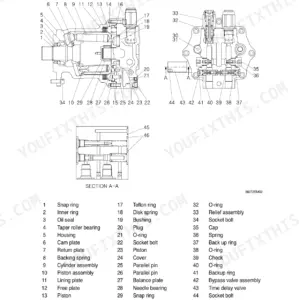
| Structure and Function | 48-131 | Pump Device, Main Control Valve, Swing Device, Travel Device |
| Hydraulic System | 132-161 | Hydraulic Circuit, Main Circuit, Pilot Circuit, Combined Operation |
| Electrical System | 162-199 | Component Location, Electrical Circuit, Monitoring System, Electrical Component Specification, Connectors |
| Mechatronics System | 200-230 | Outline, Mode Selection System, Automatic Deceleration System, Engine Speed Up Down Function, Power Boost System, Engine Speed Sensing Function, Battery Charge Warning Function |
| Troubleshooting | 231-288 | Before Troubleshooting, Hydraulic and Mechanical System |
| Maintenance Standard | 289-326 | Operational Performance Test |
| Disassembly and Assembly | 327-480 | Precautions, Tightening Torque, Pump Device, Main Control Valve, Swing Device, Travel Device, Boom Arm and Bucket Cylinder, Work Equipment |
Quick Reference Specifications
| Specification | Value | Page |
|---|---|---|
| All Models | ||
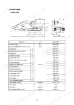
| Battery | 2 x 12V x 160Ah | p. 43 |
| Alternator | DAC HC60(24V-60AMP) | p. 43 |
| Main pump capacity | 2 x 130cc/rev | p. 43 |
| Main pump maximum pressure | 320kg/cm2 (4550psi) [350kg/cm2 (4980psi)] | p. 43 |
| Alternator check contact | 0.2 Ω (for terminal B+ - I) | p. 196 |
| Hydraulic oil temperature | 105 ± 2°C | p. 246 |
| Track roller mounting bolt | 54.7 ± 6.0 kgf·m | p. 331 |
| Swing bearing upper part mounting bolt | 97.8 ± 10 kgf·m | p. 331 |
| Swing bearing lower part mounting bolt | 97.8 ± 10 kgf·m | p. 331 |
| Mounting bolt | 58.4kgf·m (422.4lb·ft) | p. 383 |
| ROBEX 320-3 | ||
| Operating weight, ROBEX 320-3 | 30150 kg | p. 18 |
| ROBEX 320LC-3 | ||
| Operating weight, ROBEX 320LC-3 | 31200 kg | p. 19 |
Hyundai ROBEX 320-3, ROBEX 320LC-3, ROBEX 320NLC-3 Common Problems This Manual Covers
Hyundai Robex 320LC-3 hydraulic pump whining and cavitation noise, boom and arm slow with weak digging force
Check hydraulic oil level and suction line for air leaks first; cavitation usually means intake restriction. Test main relief pressure at the pump, spec is 320 kg/cm2 (4550 psi) per the specifications on page 43. If pressure won't hold, work through the hydraulic troubleshooting procedures starting on page 231 before condemning the pump.
Manual Section: Hydraulic System Troubleshooting p. 231Battery charging warning lamp stays on, batteries go dead overnight after alternator swap
Test alternator output with the engine at high idle; normal charging voltage is 24 to 27.5 V, and terminal B+ to I should read 0.2 ohms per page 196. Load-test both 12V 160Ah batteries and clean the ground strap connections. Trace the charging lamp circuit through the wiring diagram on page 164 if voltage checks pass.
Manual Section: Electrical System Troubleshooting p. 164All hydraulic functions dead, engine runs fine but both joysticks do nothing
Check the safety lever and safety solenoid first; a stuck solenoid kills all pilot pressure. Verify gear pump pilot pressure, maximum is 40 kg/cm2 (570 psi) per page 44. If pressure is low, pull and clean the pilot supply valve filter, then trace the pilot circuit in the hydraulic system section starting on page 132.
Manual Section: Hydraulic System p. 132Track rollers leaking oil, squealing on travel, and roller bolts backing out
Replace any roller with visible seal leakage; a dry roller flat-spots fast. Torque track roller mounting bolts to 54.7 kgf·m per the tightening torque table on page 331, and recheck after eight hours of travel. Follow the roller removal steps in the disassembly section beginning on page 327.
Manual Section: Disassembly and Assembly p. 331Hydraulic oil temperature lamp comes on during heavy digging, oil looks cloudy
Drain and inspect the hydraulic oil; cloudy oil means water or air contamination. Blow out the oil cooler fins from the back side and check that engine oil sits at the full mark, capacity is 21.9 L per page 43. Work through the cloudy-oil and high-temperature checks in the troubleshooting section starting on page 231.
Manual Section: Hydraulic System Troubleshooting p. 231Frequently Asked Questions
What are the replacement specifications for hydraulic oil?
The hydraulic tank capacity is 270 liters (71.3 U.S. gal) and the total system capacity is 400 liters (105.7 U.S. gal). Recommended hydraulic oils include ISO VG 32, ISO VG 46, or ISO VG 68 depending on the ambient temperature. p. 47
What is the tightening torque for the engine mounting bolts?
The engine mounting bolts and nuts (M12 x 1.75) should be tightened to a torque of 12.2 ± 1.3 kgf·m (88.2 ± 9.4 lbf·ft). p. 330
What is the procedure for bleeding air from the hydraulic pump after installation?
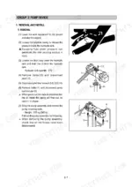
After installing the pump, remove the air vent plug (2EA), tighten it lightly, start the engine at low idling, and check that oil comes out from the plug. Once oil flows, tighten the plug fully and run the engine at low idling for 3-5 minutes to circulate the oil. p. 334
What is the standard clearance for the track roller shaft and bushing?
The standard clearance between the track roller shaft and bushing is 0.140 to 0.442 mm, with a clearance limit of 1.5 mm. p. 321
What is the standard clearance for the idler side clearance?
The standard clearance for the idler (both sides) is 0.4 to 1.0 mm, with a clearance limit of 2.0 mm. p. 323
Is this Hyundai Robex 320-3 Shop Manual a digital download?
Instant PDF download. You get the full 480-page searchable Shop Manual immediately after payment. Open it on your laptop, tablet, or phone right in the shop.
Am I free to print this Hyundai Robex 320-3 Shop Manual?
Yes. Many buyers print one chapter at a time for their own shop and keep the rest on a tablet.








Reviews
There are no reviews yet.