
Part of the Hyundai Repair Manuals.
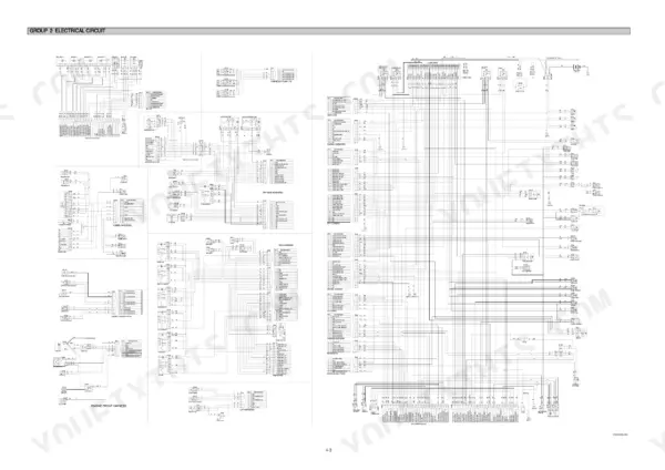
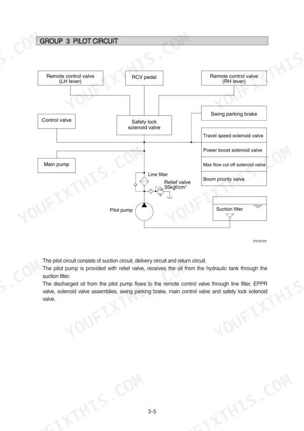
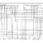
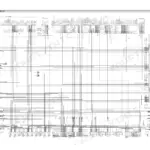
All 507 pages of this Hyundai R370LC-7 Service Manual PDF cover one machine: the R370LC-7 crawler excavator, from main pump and control valve to swing device, travel motors, and undercarriage. Inside you get complete electrical circuit diagrams, full hydraulic schematics with fluid routing, and a heavy troubleshooting section that walks boom, arm, swing, and travel faults back to the failed component. The mechatronics chapters explain the self-diagnostic system, power boost, and auto-deceleration so you can read what the machine is telling you. Set the pilot relief valve at 35 kgf/cm2 and confirm both 12V 160Ah batteries before chasing electrical gremlins. Machine down and the clock running? Get factory numbers, not forum guesses. Bookmarked with a full text layer; jump to a section or search any spec, on any device in the shop.
What's Inside This Hyundai R370LC-7 Manual
| System | Pages | Key Topics |
|---|---|---|
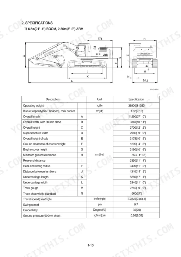
| General | 9-38 | Safety Hints, Specifications |
| Structure and Function | 39-124 | Pump Device, Main Control Valve, Swing Device, Travel Device, Rcv Lever, Rcv Pedal |
| Hydraulic System | 125-156 | Hydraulic Circuit |
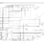
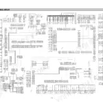
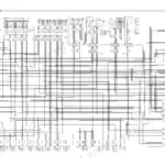
| Electrical System | 157-204 | Component Location, Electrical Circuit |
| Mechatronics System | 205-241 | Mode Selection System, Automatic Deceleration System, Power Boost System, Travel Speed Control System, Engine Overheat Prevention System, Self-Diagnostic System |
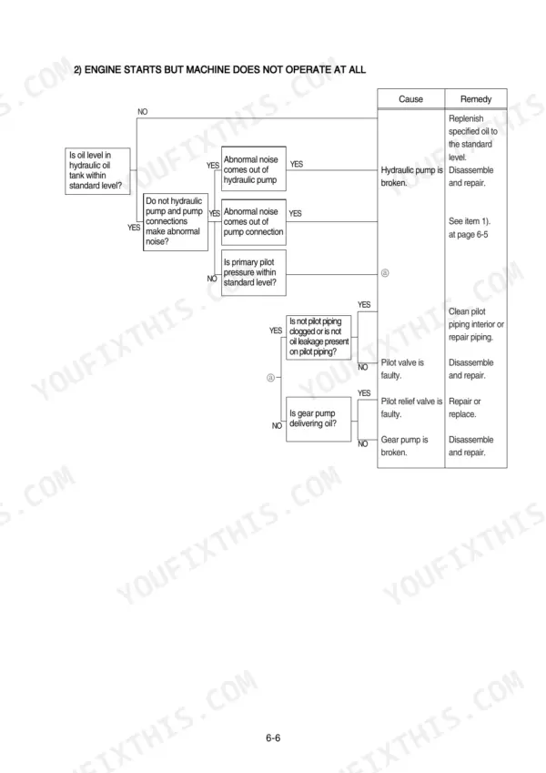
| Troubleshooting | 242-297 | Hydraulic and Mechanical System, Electrical System, Mechatronics System, Boom or Arm Action, Swing Motion, Travel Speed Control |
| Maintenance Standard | 298-335 | Main Pump, Main Control Valve, Swing Device, Travel Motor, Work Equipment |
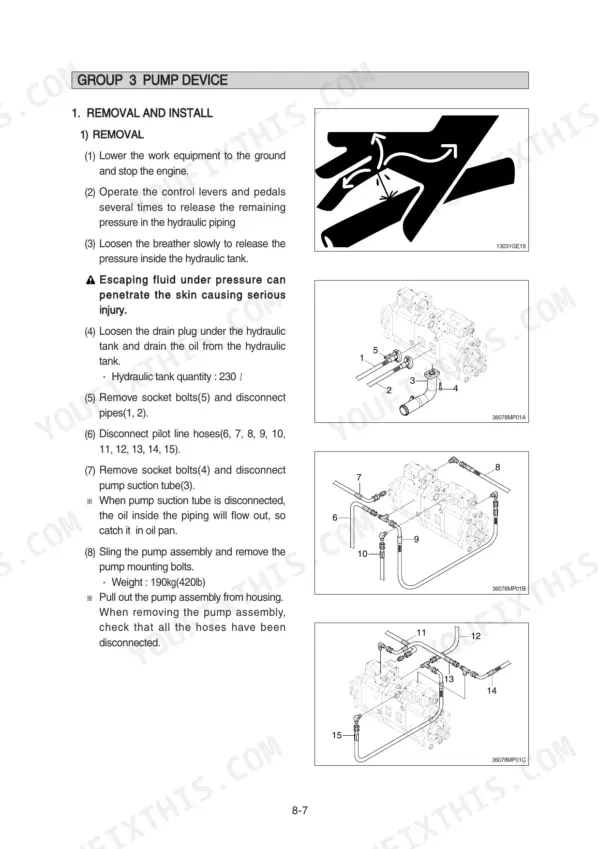
| Disassembly and Assembly | 336-492 | Pump Device, Main Control Valve, Swing Device, Travel Device, Boom Arm and Bucket Cylinder, Undercarriage |
| Component Mounting Torque | 493-507 | Engine System, Electric System, Hydraulic System, Undercarriage, Structure, Work Equipment |
Quick Reference Specifications
| Specification | Value | Page |
|---|---|---|
| bypass relief valve opening pressure | 1.5kgf/cm2 (21psi) | p. 128 |
| pilot relief valve setting pressure | 35kgf/cm2 | p. 130 |
| drain oil pressure bypass setting | 1.5kgf/cm2 (21psi) | p. 129 |
| Battery | 12V 160Ah | p. 178 |
| Pressure gauge capacity | 0 to 40-50 kgf/cm² (0 to 580-725 psi) | p. 227 |
| EPPR valve pressure specification | 2-25 kgf/cm² (30-350 psi) | p. 227 |
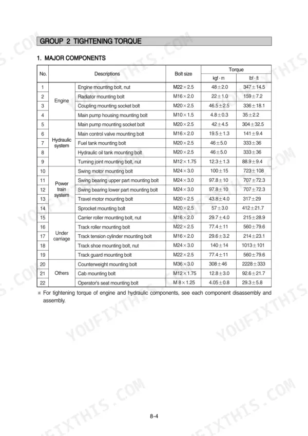
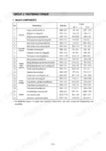
| Swing motor mounting bolt | 100±15 kgf·m | p. 340 |
| Main pump housing mounting bolt | 4.8±0.3 kgf·m | p. 340 |
| Main pump mounting socket bolt | 42±4.5 kgf·m | p. 340 |
| Track tension cylinder mounting bolt | 29.6±3.2 kgf·m | p. 340 |
| Swing motor mounting bolt (Item 11) | 100 ± 15 kgf·m | p. 499 |
| Adjust component mounting bolt (Item 3) | 13.3 ± 2.7 kgf·m | p. 502 |
Hyundai R370LC-7 Common Problems This Manual Covers
Hyundai R370LC-7 hydraulic pump whines under load, boom and arm lift slow and weak
Check hydraulic oil level and top up before condemning the pump. Replace the return filter; a clogged element opens the bypass relief at 1.5 kgf/cm2 (21 psi) and sends unfiltered oil straight to the tank. Inspect the suction line for air leaks, then work through the hydraulic troubleshooting procedures starting.
Manual Section: Hydraulic and Mechanical System Troubleshooting p. 128Engine cranks slowly or will not crank at all after machine sits overnight
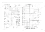
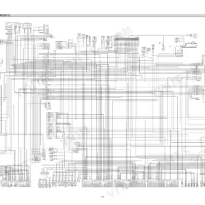
Load-test both batteries; this machine runs two 12V 160Ah units and one weak battery drags the whole system down. Clean and tighten the ground strap between frame and engine block, check the main fuses, then trace the start circuit on the wiring diagram on page 160 if cranking stays slow.
Manual Section: Electrical System Troubleshooting p. 178Swing motion is jerky and machine pulls to one side when traveling under load
Test swing and travel relief pressures before tearing into the motors. Compare swing and travel relief readings against the pressure settings in the General specifications. Low readings point to a stuck relief valve or worn motor. Swap the travel lines side to side to isolate a weak motor from a control valve fault.
Manual Section: Hydraulic and Mechanical System Troubleshooting p. 35Engine speed hunts, power drops in every work mode, auto decel acts erratic
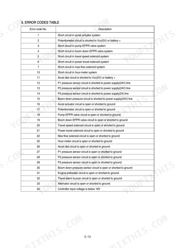
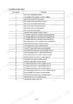
Connect a pressure gauge to the EPPR valve output port and cycle through the work modes. Output should track within the EPPR valve pressure specification of 2 to 25 kgf/cm2 given on page 227. Readings outside that band mean a sticking EPPR spool or a bad signal; check connector voltage and the error code reference on page 217 before replacing the valve.
Manual Section: Mechatronics System Troubleshooting p. 283Hydraulic oil temperature climbs into the red zone after an hour of steady digging
Blow out the hydraulic oil cooler with compressed air from the back side; packed fins are the usual culprit. Replace the drain cartridge filter, since a plugged element bypasses at 1.5 kgf/cm2 (21 psi) and lets hot unfiltered case drain oil keep circulating. If temperature still climbs, run the hydraulic oil checks starting.
Manual Section: Hydraulic and Mechanical System Troubleshooting p. 129Frequently Asked Questions
What is the procedure to check the electric current at the EPPR valve?
To check the electric current, start the engine, set the machine to S-mode, and cancel the auto-decel mode. Position the accel dial at 10 (MAX). If the tachometer shows approximately 1700 ± 100 rpm, disconnect one wire harness from the EPPR valve and install a multimeter. The specification for the current is 200-450mA. p. 283
What is the replacement interval for the gear oil in the travel reduction gear?
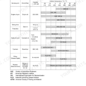
The gear oil in the travel reduction gear should be replaced for the first time at 500 hours, and then every 2000 hours thereafter. After disassembling, fill with new oil without fail. p. 325
What is the tightening torque for the main pump mounting socket bolts?
The tightening torque for the main pump mounting socket bolts (M20 x 2.5) is 42 ± 4.5 kgf·m (304 ± 32.5 lbf·ft). p. 340
How do I bleed the air from the hydraulic pump after installation?
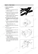
To bleed the air, remove the two air vent plugs from the pump. Tighten the plugs lightly, start the engine at low idling, and wait until oil comes out from the plugs. Finally, tighten the plugs fully. p. 344
What is the standard engine speed for the R370LC-7 in M mode?
The standard engine speed for the R370LC-7 in M mode is 1900 ± 50 rpm. p. 302
Is this Hyundai R370LC-7 manual a PDF I download?
A single searchable PDF file of 507 pages, downloadable right after payment. Nothing ships, nothing waits in the mail.
Can I print just the pages I need from this Hyundai R370LC-7 manual?
Yes. Print the pages or sections you need for your own shop use. Any standard printer works.






Reviews
There are no reviews yet.