Part of the Hyundai Repair Manuals.
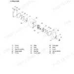
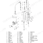
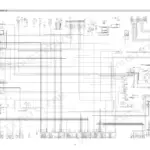
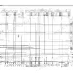
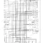
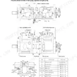
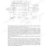
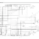
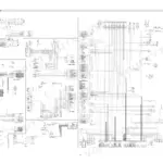
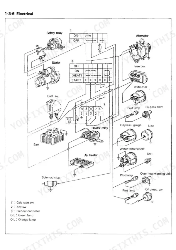
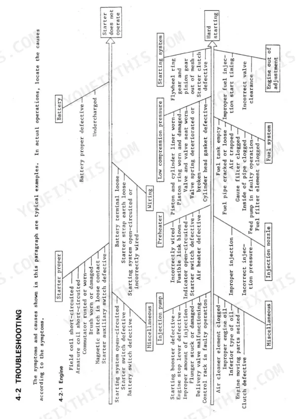
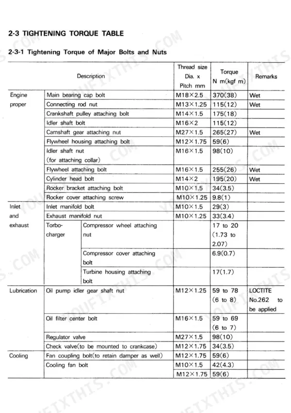
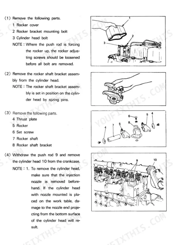
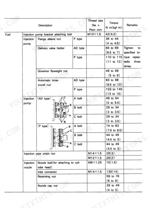
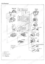
Hyundai's own factory shop manual for the D6A diesel engine family, this 317-page Hyundai D6AC shop manual PDF also covers the D6AU and D6AZ. Thirteen chapters run from engine section views and specifications through service standards, special tools, adjustment and break-in, then the engine proper: cylinder head, valve mechanism, crankcase, cylinder liner, piston and crankshaft. Wiring diagrams sit in the General chapter, troubleshooting charts back up the compression, oil consumption and oil pressure checks that decide time to overhaul, and the fuel chapter works through the injection pump, governor, automatic timer and injection nozzle. Set nozzle injection pressure to 220 kgf/cm². The thermostat should start opening at 71°C. Adjusting valve lash, you set 0.4 mm inlet and 0.6 mm exhaust with the engine cold, figures taken straight from the engine adjustment standards. Bookmarked and text-searchable, your copy travels wherever the engine sits, tightening torque table and valve clearances included.
What's Inside This Hyundai D6AU, D6AZ, D6AC, D6A Manual
| System | Pages | Key Topics |
|---|---|---|
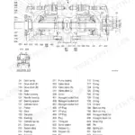
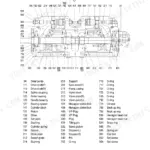
| General | 5-66 | Engine Section Views, Engine Number, Nameplate, Specifications, Construction, Operation |
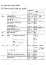
| Service Standards | 67-82 | Engine Adjustment Standards, Service Standards Table, Tightening Torque Table, Sealant and Grease Table |
| Special Tools | 83-86 | Engine Tools, Injection Pump Tools, Valve Mechanism Tools, Cylinder Liner Tools |
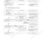
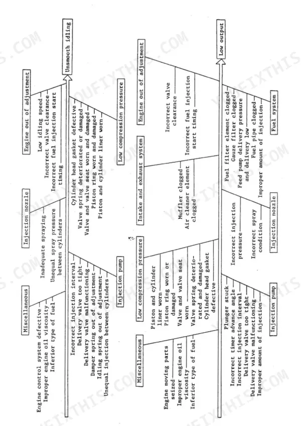
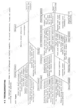
| Determining Time to Overhaul | 87-94 | Compression Pressure Measurement, Oil Consumption, Oil Pressure, Troubleshooting |
| Engine Adjustment and Break-In Operation | 95-103 | Valve Clearance, Fuel Injection Timing, Engine Speed Adjustment, V-Belt Tension, Break-In Operation |
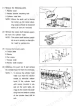
| Removal and Installation of Auxiliaries | 104-117 | Electrical Parts, Intake Air Heater, Air Cleaner, Turbocharger, Fuel Filter, Injection Pump |
| Engine Proper | 118-176 | Cylinder Head, Valve Mechanism, Crankcase, Cylinder Liner, Piston, Crankshaft |
| Inlet and Exhaust | 177-194 | Air Cleaner, Dust Indicator, Turbocharger, Exhaust Manifold |
| Lubrication | 195-201 | Oil Pump, Oil Filter, Oil Cooler, Relief Valve, Regulator Valve, Oil Jet |
| Cooling | 202-207 | Water Pump, Thermostat, Fan, V-Belt, Radiator |
| Fuel | 208-288 | Injection Pump, Governor, Feed Pump, Automatic Timer, Injection Nozzle, Fuel Filter |
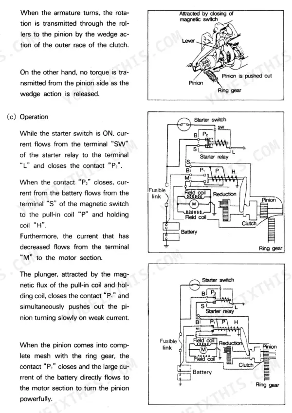
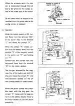
| Electrical | 289-311 | Starter, Starter Relay, Alternator, Intake Air Heater, Heater Relay |
| Other Equipment | 312-317 | Injection Pump Drive, Automatic Stop System, Stop Solenoid, Oil Pressure Switch, Water Temp Unit |
Quick Reference Specifications
| Specification | Value | Page |
|---|---|---|
| Oil bypass alarm on start pressure | 295 to 345 kPa | p. 199 |
| Oil pump spring installed length | 46.3 mm | p. 197 |
| Thermostat valve opening temperature | 71°C | p. 13 |
| Injection pressure | 220kgf/cm² | p. 14 |
| Valve clearance (when cold) Inlet side | 0.4 mm | p. 67 |
| Valve clearance (when cold) Exhaust side | 0.6 mm | p. 67 |
| Oil pressure (oil temperature : 70°C) Air idling speed Standard value | 145 to 290 kPa | p. 67 |
| Oil pressure (oil temperature : 70°C) Air idling speed Repair limit | 49 kPa | p. 67 |
| Water pump interference between pump shaft and pulley | 0.05 to 0.08 mm | p. 74 |
| Water pump interference between pump shaft and impeller | 0.04 to 0.06 mm | p. 74 |
| Thermostat valve opening start temperature | 69 to 73 °C | p. 74 |
| Bend lock washer torque | 7 N m (0.7 kgf m) | p. 190 |