

Part of the Hyundai Repair Manuals.
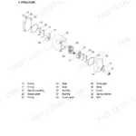
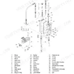
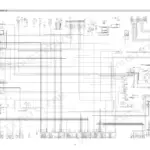
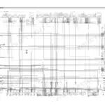
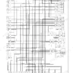
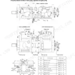
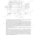
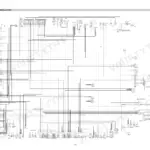
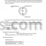
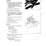
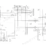
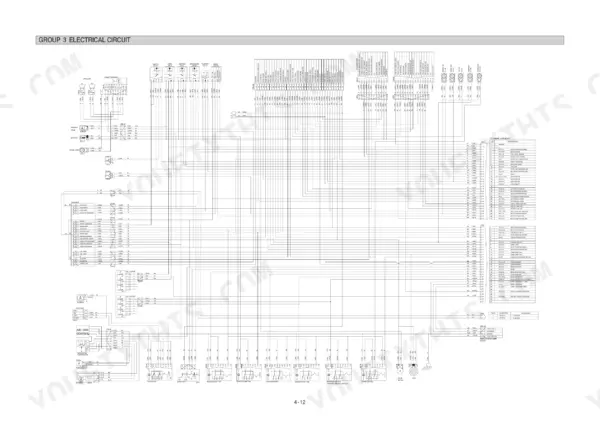
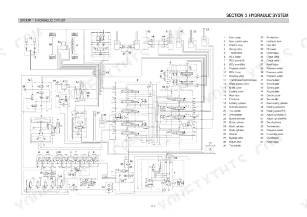
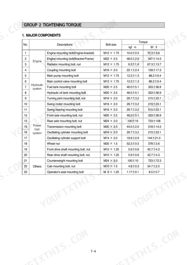
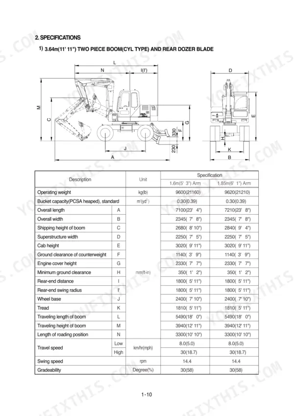
Every one of the 574 pages in this Hyundai R95W-3 Service Manual PDF is aimed at a single machine: the R95W-3 wheeled excavator, from the main pump to the rear axles. You get full hydraulic circuit schematics, electrical wiring diagrams with component locations, and exploded views covering the main control valve, swing motor, travel reduction gear, and transmission. A complete troubleshooting section walks the hydraulic and mechanical systems fault by fault, backed by a metric bolt torque chart and operational performance tests for checking a tired machine against factory numbers. Set the pilot relief valve at 40 kg/cm2, then pull the turning joint mounting bolts to 29.7 kgf.m before you button anything up. Tired of guessing which relief valve is bleeding your pressure? Bookmarked and keyword-searchable; download it, pull it up beside the machine, and get back to work.
What's Inside This Manual
| System | Pages | Key Topics |
|---|---|---|
| General | 1-28 | Safety Hints, Specifications |
| Structure and Function | 29-102 | Pump Device, Swing Device, Main Control Valve, Travel Device, Rcv Lever |
| Hydraulic System | 103-131 | Hydraulic Circuit, Main Circuit |
| Electrical System | 132-190 | Component Location, Monitoring System, Electrical Circuit |
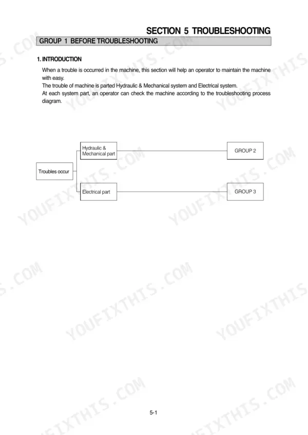
| Troubleshooting | 191-228 | Before Troubleshooting, Hydraulic and Mechanical System |
| Maintenance Standard | 229-239 | Operational Performance Test, Major Components, Track and Work Equipment |
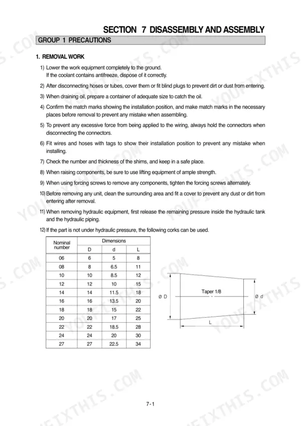
| Precaution and Tightening Torque | 240-246 | Removal Work, Installation Work, Tightening Torque, Metric Bolt Torque Chart |
| Pump Device | 247-252 | Removal, Installation, Main Pump Disassembly, Gear Pump Disassembly |
| Main Control Valve | 253-288 | Tools and Jig, Disassembly, Assembly, Relief Valve, Port Plug |
| Swing Device | 289-304 | Relief Valve, Swing Motor Removal, Swing Motor Disassembly, Swing Motor Assembly |
| Travel Device and Reduction Gear | 305-314 | Reduction Gear Removal, Reduction Gear Disassembly, Reduction Gear Assembly, Motor Unit, Regulator |
| Rcv Lever and Accelerator Pedal | 315-343 | Rcv Lever Disassembly, Rcv Lever Assembly, Accelerator Pedal Disassembly, Accelerator Pedal Assembly |
| Turning Joint, Steering Valve, and Transmission | 344-430 | Turning Joint Removal, Steering Valve Disassembly, Transmission Removal, Transmission Disassembly, Transmission Assembly |
| Axles and Work Equipment | 431-574 | Front Axle Removal, Rear Axle Removal, Steering Cylinder, Bucket Cylinder, Arm Cylinder, Boom Cylinder |
Quick Reference Specifications
| Specification | Value | Page |
|---|---|---|
| Bypass check valve setting pressure | 1.5kg/cm2 (21psi) | p. 105 |
| Bypass relief valve opening pressure | 3.0kg/cm2 (43psi) | p. 105 |
| Fuel low level lamp threshold | 22 L | p. 141 |
| Turning joint mounting bolt, nut | 29.7±3.2 kgf·m | p. 244 |
| Main pump mounting bolt | 12.2±1.3 kgf·m | p. 244 |
| Engine Oil Capacity | 10L | p. 28 |
| Hydraulic Tank Capacity | 90L | p. 28 |
| Engine Rated Gross Horse Power | 77Hp | p. 24 |
| Main Pump Rated Pressure | 280kgf/cm2 | p. 24 |
| Swing Motor Relief Pressure | 190kgf/cm2 | p. 25 |
| Travel Motor Relief Pressure | 280kgf/cm2 | p. 25 |